
This project is for simple 9V AC to 38V DC Voltage Tripler Circuit and it converts low AC voltage into higher DC voltage, also the input is 9V AC from transformer and the output is around 38V DC without load.
Furthermore, it is easy to build as it uses common parts and therefore, it is good for beginners and basically, this circuit uses diodes and capacitors and these parts multiply the peak voltage.
As a result, we get higher DC voltage than normal rectifier, but however the current capacity is low, so it is suitable for small current applications.
Circuit Working:
Parts List:
| Components | Values | Quantity |
|---|---|---|
| Capacitors | Electrolytic 470uF 63V | 3 |
| Semiconductors | Rectifier Diodes 1N4007 | 3 |
| Transformer 220V AC Primary to 9V AC Secondary | 1 | |
| Input Supply 220V AC 50Hz | 1 | |
| Output Voltage approximately 38V DC | 1 |
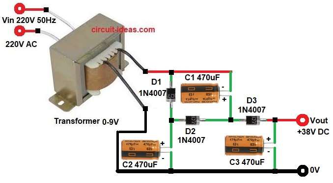
First, the transformer reduces 220V AC to 9V AC, so the secondary gives 9V AC RMS.
Next, during positive half cycle diode D1 conducts and capacitor C1 charges to peak voltage of AC, the peak voltage of 9V AC is about 12.7V and therefore, C1 charges near 12V DC.
Then during negative half cycle diode D2 conducts and capacitor C2 charges and it adds voltage of C1 and AC input and as a result, C2 stores nearly double peak voltage.
After that, diode D3 conducts in next cycle and C3 charges by adding voltage of C1 and C2 and therefore, total output becomes nearly three times peak voltage.
Finally, we get about 3 × 12.7V = 38V DC at output without load.
However, the output voltage decreases under load as the capacitors discharge while supplying current.
Therefore, this circuit known as a voltage tripler because it increases the peak input voltage to approximately three times its value.
Formula with Calculation:
Formula with calculation for output voltage:
Vrms = 9V
Vpeak = Vrms × 1.414
= 9 × 1.414
Vpeak = 12.726V
Vdc (ideal tripler) = 3 × Vpeak
= 3 × 12.726
Vdc = 38.178V
So output voltage is approximately 38V DC without load.
How to Build:
To build a 9V AC to 38V DC Voltage Tripler Circuit follow the below circuit connection steps:
- First, gather all the components as shown in circuit diagram.
- Next, transformer primary side one end connect to 220V AC Live, transformer other end connect to 220V AC natural side, transformer secondary side one end connect to diode D1 anode an capacitor C1 negative and then transformer secondary other end connect to 0V
- After that, diode D1 anode connect to secondary upper end and cathode connect to positive terminal of C2 and anode of diode D2
- Now capacitor C1 positive end connect between diode D2 cathode and diode D3 anode and C1 negative connect to transformer secondary upper pin.
- Further, capacitor C2 positive end connect to cathode of D1 and anode of D2 and negative connect to ground
- Also, diode D3 anode connect to junction of D2 cathode and C1 positive and cathode connect to Vout terminal.
- Finally, capacitor C3 positive connect to cathode of D3 and Vout and negative connect to ground
Important Notes:
- Use 50V or 63V higher rated capacitors, because output is around 38V.
- Check diode direction carefully as wrong direction will not work.
- As the output current is low, do not connect heavy load.
- Always use isolated transformer for safety.
Conclusion:
To conclude, this 9 V AC to 38 V DC Voltage Tripler Circuit offers a simple, low cost design, as it uses only three diodes and three capacitors, making it easy to build.
However, it gives high voltage but low current, so it is good for small DC applications, testing or experiments and if we need more current then use transformer with higher rating and bigger capacitors.
Finally, this circuit is good example to understand voltage multiplier concept in simple way.