This circuit shows a Low Current Controlled Battery Charger Circuit using LM723 IC and 2N3055 power transistor.
Furthermore, this design mainly gives constant charging current to battery, so battery gets safe charging without over current damage.
First, AC supply comes from transformer and then circuit converts it into DC and after that LM723 controls voltage and current.
Then 2N3055 transistor increases current capacity for battery charging; hence, this circuit works well for small 12V battery charging at low current range.
Circuit Working:
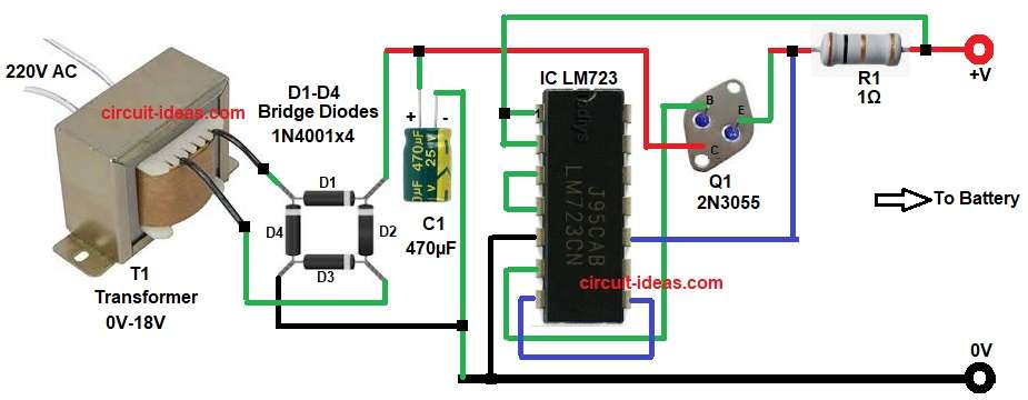
Parts List:
| Components | Values | Quantity |
|---|---|---|
| Resistor | 1Ω 2 watt | 1 |
| Capacitor | Electrolytic 470µF 25V | 1 |
| Semiconductors | IC LM723 Voltage regulator IC | 1 |
| Power pass transistor 2N3055 | 1 | |
| Heatsink 2N3055 | 1 | |
| Bridge Diodes D1-D4 1N4001 | 4 | |
| Step-down transformer Primary 220V AC Secondary 0V–18V AC | 1 |
First, 220V AC supply goes into step down transformer T1, then this transformer reduces voltage from 220V AC to around 18V AC.
Then this AC voltage enters bridge rectifier made using diodes D1 to D4 and this bridge rectifier converts AC into DC.
After that capacitor C1 smooths the DC voltage and reduces ripple, s we get stable DC supply at input side.
Now LM723 IC starts working as voltage and current controller; LM723 compares output voltage with internal reference voltage and it adjusts output drive accordingly.
Then 2N3055 transistor works as pass transistor and it handles high current load, also LM723 alone cannot supply high current, so 2N3055 boosts current for battery charging.
Resistor R1 controls charging current and in this circuit R1 value decides constant current flow into battery.
When battery is low, circuit supplies constant current and when battery reaches set voltage (around 7.5V) then charging current reduces and battery becomes safe.
Hence, this circuit mainly works in constant current mode, so battery life increases and overheating reduces.
Note:
Output voltage generally set around 7.5V for small battery charging purpose and LM723 helps to keep voltage stable; so battery does not overcharge.
How to Build:
To build a Low Current Controlled Battery Charger Circuit using LM723 IC follow the below connection steps:
- Start, the circuit by assembling all the parts as shown in diagram above.
- First, connect transformer primary to 220V AC supply carefully.
- Then connect secondary 18V AC output to bridge rectifier (D1 to D4).
- After that, connect capacitor C1 across rectifier output for filtering.
- Next, connect LM723 IC on breadboard or PCB.
- Then connect pin 1 and pin 2 of IC to positive supply.
- Join pin 3 and pin 4 of IC and pin 5 of IC goes to ground.
- Then pin 6 Vref pin of IC goes to base pin of transistor Q1.
- Also, join pin 7 and 8 of IC.
- Pin 10 of IC also connects to positive supply.
- Connect emitter of 2N3055 to output terminal going to battery positive.
- Connect collector of 2N3055 to DC positive input line.
- Then place R1 in series for current sensing and limiting.
- Finally, connect battery at output terminals with correct polarity.
Conclusion:
This Low Current Controlled Battery Charger Circuit using LM723 IC gives simple and reliable constant current charging solution.
Moreover, it uses 2N3055 transistor to handle high current and LM723 IC to control voltage and current; so battery charges safely without damage.
Lastly, this design works best for small 12V battery charging applications and hobby electronics projects.

Leave a Reply