Tone Controller Circuit using IC TL072 Op-amp changes treble and bass sound, as it makes sound better and let us control treble and bass.
Also, parts connect in order to cut or boost some sound frequencies.
Circuit Working:
Parts List:
| Components | Values | Quantity |
|---|---|---|
| Resistors (All resistors are 1/4 watt unless specified) | 1k | 2 |
| 100k | 2 | |
| 10k | 2 | |
| 2.2M | 1 | |
| Potentiometer 100k | 4 | |
| Capacitors | Ceramic 220nF | 1 |
| Electrolytic 1μF 25V | 1 | |
| Electrolytic 100μF 25V | 1 | |
| Electrolytic 2.2μF 25V | 2 | |
| Electrolytic 22μF 25V | 2 | |
| Semiconductors | IC TL072 | 1 |
To begin with, this tone control circuit uses special amplifier chip called TL072 and with few extra parts it give clear sound with very low noise; also, it needs both positive and negative power to work well.
Here how the circuit works:
First sound signal goes through TL072 chip and this chip make weak signal strong like turning up volume, then signal goes to tone control part.
Here we used knobs to adjust bass, treble and volume and resistors R2 and R3 help control how amplifier works.
After boosting signal goes to tone control section where we can change sound balance and at end volume knob VR2 adjust how loud sound goes to speaker.
Also, balance knob VR3 change sound level to each speaker in stereo system.
Formulas:
TL072 is dual op-amp chip, as it is good for audio and tone control because it has low noise and fast signal change with high slew rate and tone control design uses TL072 like this:
1. Filter Design:
We can use the TL072 in filter circuits such as the Sallen–Key filter and for a low-pass filter, we calculate the cutoff frequency as:
fc = 1 / 2πRC
where:
- R is the resistor
- C is the capacitor
We can change R and C to set the frequency.
2. Gain Calculation:
Gain (Av) shows how much the amplifier increases the input signal and we can adjust the gain by selecting appropriate resistor values, so for a non-inverting amplifier, the gain is:
Av = 1 + Rf / Rin
where:
- Rf is the feedback resistor
- Rin is the input resistor
Use this formula for bass, mid and treble stages.
Final Tip:
Choose resistor and capacitor values based on what sound we want like for more bass, less treble, etc, as this help make custom tone circuit with TL072.
How to Build:
To build a Tone Controller Circuit using IC TL072 Op-amp follow the below mentioned steps for connections:
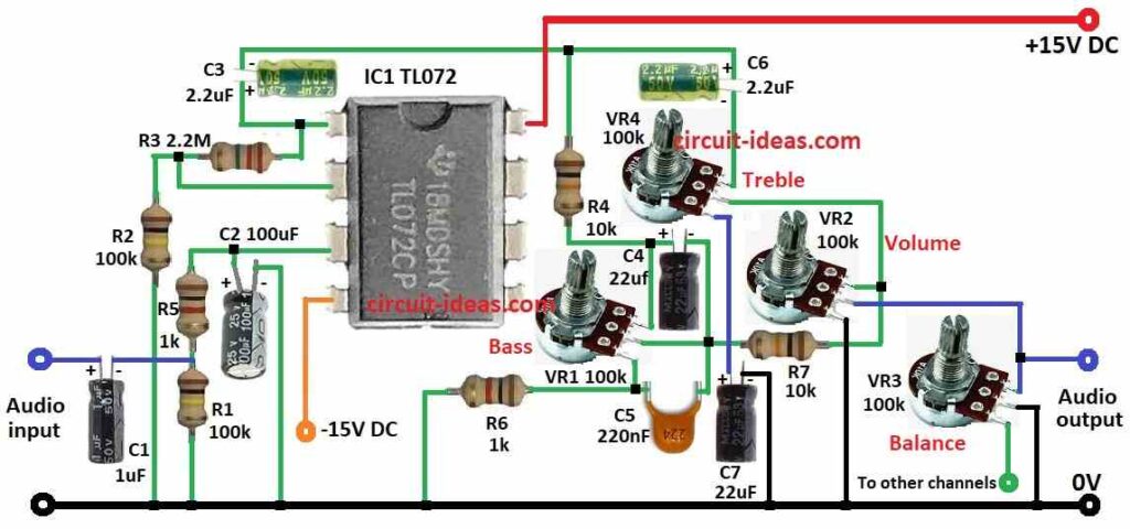
- First, make circuit like diagram shown above and gather all the circuit parts.
- Next, connect pin 1 of IC1 TL072 to VR4 top leg using C3 and C6 capacitors and from pin 1 connect R3 resistor to ground through R2.
- Then pin 2 connect in middle of R3 and R2.
- After that, pin 3 goes to C2 capacitor and then C2 goes to ground.
- From (+) side of C2 connect R5 and R1 to ground and audio input goes between R5 and R1 through C1 capacitor.
- Then pin 4 of IC1 goes to -15V and pin 8 goes to +15V power.
Potentiometer VR connections:
- Now VR1 top leg connect to pin 1 of IC1 through R4, VR1 center leg connect to top leg of VR2 using R7 and VR1 last leg connect to ground through R6.
- Next, VR2 top leg connect to VR4 center leg, VR2 center leg goes to VR3 top leg and then to audio output and then VR2 last leg goes to ground.
- Then VR3 top leg connect to VR2 center leg, VR3 center leg goes to ground and then VR3 last leg goes to other channel for stereo.
- Lastly, VR4 top leg connect to pin 1 of IC1, VR4 center leg connect to VR2 top leg via VR1 center leg and VR4 last leg goes to ground through C7 capacitor.
- Also, C4 and C5 capacitors connect between R4 and R6.
Conclusion:
Overall, this easy Tone Controller Circuit using IC TL072 Op-amp work like mini sound booth, also it boost weak sound signal like turning up mic volume.
Hence, with this we can become a DJ and change bass, treble, volume; but just be careful with parts especially the capacitors and use correct power supply.
Leave a Reply