Many electronic things need clean DC power to work good and through this post we will show how to make one easy Simple Adjustable Power Supply Circuit.
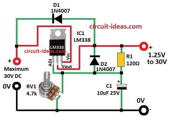
The circuit changes dirty DC power to clean power and it uses one chip called LM338, the circuit take DC from 5 to 34 volt and gives clean DC from 1.25 to 30 volt.
Also, we can turn one knob to get voltage what our device need.
Circuit Working:
Parts List:
| Components | Values | Quantity |
|---|---|---|
| Resistors | 120Ω 1/4 W | 1 |
| Potentiometer 4.7k | 1 | |
| Capacitors | Electrolytic 10µF 25V | 1 |
| Semiconductors | IC LM338 | 1 |
| Diode 1N4007 | 2 |
To begin with, pin 3 (Vin) of LM338 chip connects to DC power input and this input can range between 5V to 34V which is not stable.
Also, IC LM338 has smart parts inside with one voltage reference of 1.25V and one error amplifier and this error amplifier checks output voltage and compares it with 1.25V reference.
A moving resistor (RV1) connects pin 1 Adjust to ground and by turning RV1, the user changes the voltage, which also changes the output voltage.
Additionally, two resistors, R1 and R2 form a voltage divider, and we can calculate the 1.25V output voltage using their values and the formula below.
Pin 2 Vout is output pin which gives final smooth voltage and user can control output voltage from 1.25V to 30V by changing R1 and RV1.
Maximum current from LM338 is 5 Amps.
Capacitor C1 helps soft start and it slowly gives power to load and diodes D1 and D2 stop damage if someone connect power in wrong way.
Resistor, capacitor and LM338 together give clean and stable output voltage, as LM338 is good for devices where power changes and it keeps voltage steady even if load changes.
Also, it can give 5 Amp constant current at max.
Formulas:
This is the formula to find output voltage (Vout) for a circuit using adjustable voltage regulator like LM338:
Vout = 1.25V × (1 + R2 / R1) + Iadj × R2
where,
- Vout is the output voltage we want.
- The LM338 uses a fixed 1.25V reference voltage, which is the same as in the LM317.
- R1 and R2 are two resistors we connect outside the chip and they help set the output voltage.
- Iadj is a very small current from the Adjust pin which is usually so small we can ignore it.
How to find Vout:
Know the values:
First, we must know values of R1, R2 and maybe Iadj.
Also, we picked R1 and R2 depending on how much output voltage we need and check the LM338 datasheet to pick good values.
Calculate the middle part:
First calculate (1 + R2 / R1) and this is from the two resistors, where if R2 is bigger than R1 then Vout goes higher.
Use the formula:
After that use the full formula:
Vout = 1.25V × (1 + R2 / R1) + Iadj × R2
Sometimes we can ignore the last part (Iadj × R2) because Iadj is very small.
Important notes:
The formula has Vout on both sides sometimes so it may not always be easy to solve, but in most simple cases it works fine.
For many uses, just using the first part 1.25×(1+R2/R1) is enough.
However, to be sure Vout is correct, we use correct resistor values and sometimes Iadj matters, but mostly it does not.
How to Build:
To build a Simple Adjustable Power Supply Circuit following steps are required for connections:
- First, connect pin 3 Vin of LM338 to positive side of input power supply.
- Next, connect pin 2 Vout to the output screw terminal.
- Then connect pin 1 Adjust to ground using a moving resistor RV1.
- After that connect R1 and R2 based on the output voltage we want and use the formula from below.
- Also, turn RV1 to change and set the output voltage which gives more control.
- Next, put capacitor C1 between R1 ADJ pin and ground (GND).
- Also, be sure polarity is correct and use values from LM338 datasheet.
- Then use diodes D1 and D2 for reverse voltage protection and connect them the right way to avoid damage.
- Finally, input power should be between 1.5V to 35V to make LM338 work well.
Testing the Circuit:
- After turning ON, use a multimeter to check the output voltage.
- Turn RV1 and see how output voltage changes.
- Output voltage should stay within our needed range.
- Watch for voltage ripple and be sure voltage is steady.
- Capacitor C1 helps give soft start with slow power up.
- Check D1 and D2 to be sure reverse protection is working.
Conclusion:
Overall, by following these above easy steps we can make a Simple Adjustable Power Supply Circuit which gives clean DC output and supports voltage we choose and current up to 5 Amps.
Always be safe when working with electronics and for more details go through the IC LM338 datasheet.
Leave a Reply