This is small and simple MIC preamplifier circuit using op-amp IC LM358 and it uses op-amp to make weak sound from MIC more strong, so it boosts low audio signal into stronger one.
Also, the circuit is good to record voice or connect to speaker and it is easy to make with not many parts.
In addition, it have one knob to control how much it boosts the signal, so we can use it with different microphones or for other things.
What is a MIC Preamplifier Circuit:
Simple MIC preamplifier circuit is small electronic circuit which helps to make weak sound signal from microphone more strong and microphone gives low signal, so this circuit boosts it for use with other audio device.
Also, in sound system preamplifier checks sound is loud enough and there is no loss in noise so next step we can use it properly.
Circuit Working:

Parts List:
| Components | Values | Quantity |
|---|---|---|
| Resistors | 10k 1/4 W | 1 |
| 82k 1/4 W | 1 | |
| 820Ω 1/4 W | 1 | |
| 100k 1/4 W | 2 | |
| Capacitors | Electrolytic 1µF | 2 |
| Semiconductors | IC LM358 | 1 |
| Electret MIC | 1 |
Firstly, the main part of this simple MIC preamplifier is IC LM358 which work like inverting amplifier to make MIC signal more strong.
Here, condenser MIC give very small signal so it needs to boost it for next step.
First, one 820 ohm resistor and 1µF capacitor connect with MIC in series and this part decide input impedance, then one 82k resistor stop too much current and after that, 100k resistor gives feedback and it control how much gain (amplify) happen.
Next, C1 capacitor is coupling capacitor and it let AC sound signal go but stop DC and pin 1 is output we can connect this to speaker or other sound device.
Lastly, the circuit uses a power between 6V to 12V DC.
Formulas:
Below is the formula for Simple MIC Preamplifier Circuit using op-amp:
Gain (Av) = Vout / Vin = – (Rf / Rin)
where:
- Gain (Av) is how much signal it gets for bigger voltage gain.
- Vout / Vin is output voltage which divides by input voltage.
- Rf is feedback resistor and in this circuit it is 100k between pin 2 and 3.
- Rin input resistor and here it is 820 ohm.
This formula show how strong op-amp make the MIC signal.
How to Build:
To build a Simple MIC Preamplifier Circuit using an Op-Amp requires the below steps for connections:
- First, connect DC power supply to circuit and be sure positive and negative wire are connected correctly.
- Also, if needed put LED with 82k resistor to show power is ON.
- Next, connect MIC output to inverting pin (–) of LM358 using C1 capacitor and 820 ohm resistor.
- Then signal connects to negative pin and 100k resistor gives feedback from output to same pin.
- Also, if we use variable resistor instead of 820 ohm we can control how much input connects to op-amp.
- Then pre-amplified sound come from pin 1 of LM358 which connect this to speaker or other audio device.
Testing:
- First, turn ON the circuit and if LED is there then check it to light up.
- Then, if we use a variable resistor then adjust it to get good sound.
- Also, use audio recorder or speaker to test the output sound.
MIC Preamplifier Circuit using a Single Transistor Working:
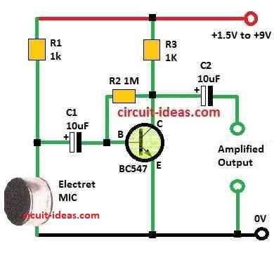
Parts List:
| Components | Values | Quantity |
|---|---|---|
| Resistors | 1k 1/4 W | 2 |
| 1M 1/4 W | 1 | |
| Capacitors | Electrolytic 10µF | 2 |
| Semiconductors | Transistor BC547 | 1 |
| Electret MIC | 1 |
In the above circuit, transistor BC547 uses common emitter and collector to base bias setup, capacitors C1 and C2 stops DC and only let audio signal go through.
So the MIC preamplifier gives clean sound with no noise or bad distortion, also this one transistor MIC preamp can work with 1.5V to 6V power.
Conclusion:
To conclude, this Simple MIC Preamplifier Circuit using op-amp is easy way to boost small audio signal, and it works good and we can change it for many audio uses.
Leave a Reply