Dynamic microphones are strong, last long and work well with loud sounds, so people use them a lot in sound systems and recording, but their signal is weak.
So they need a preamp to make sound stronger.
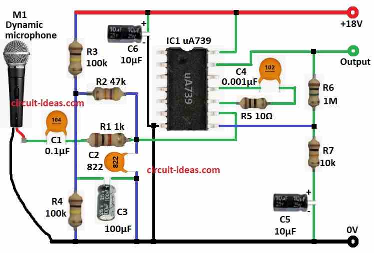
This Dynamic Microphone Preamplifier Circuit using IC uA739 is a preamp for dynamic mics, as it uses µA739 op-amp to give high gain with low distortion.
Also, it runs on +18V DC and boosts mic signals for audio use and its design gives good sound quality and works steady which is good for many audio jobs.
Circuit Working:
Parts List:
| Components | Values | Quantity |
|---|---|---|
| Resistors (All resistors are 1/4 watt unless specified) | 1k | 1 |
| 47k | 1 | |
| 10Ω | 1 | |
| 1M | 1 | |
| 10k | 1 | |
| 100k | 2 | |
| Capacitors | Ceramic 0.1µF | 1 |
| Ceramic 0.0082µF | 1 | |
| Ceramic 0.001µF | 1 | |
| Electrolytic 100µF 35V | 2 | |
| Semiconductors | IC µA739 | 1 |
| Dynamic Microphone | 1 |
This preamp circuit uses +18V DC power and when mic hears sound it makes small AC signal.
Then capacitor C1 sends this signal to pin 9 of non-inverting of IC 739 op-amp and op-amp makes signal stronger using R6, R7 and C5 as feedback parts.
Also, the op-amp provides high input impedance, so it does not stress the microphone and the gain depends on the ratio of R6 and R7 and the value of C5.
After that, stronger signal comes out from pin 13.
Now capacitor C5 at output removes DC and sends clean AC to next stage and capacitors C4 and C6 stop power noise from affecting op-amp.
Formulas with Calculations:
Here are the formulas and simple calculations for the dynamic mic preamp:
Gain:
Gain = R6 / R7
= 1M / 10k = 100
So signal gets 100 times stronger.
Low frequency cutoff (f_c):
f_c = 1 / (2 * π * R_in * C1)
In the circuit:
R_in = 47k (set by R2)
C1 = 0.1µF
f_c = 1 / (2 * 3.1416 * 47000 * 0.0000001)
f_c = 34 Hz
Hence, this keeps bass sounds but blocks very low noise.
How to Build:
To build the Dynamic Microphone Preamplifier Circuit using IC uA739 follow the below mentioned steps for connections:
- First, fix all parts as shown in the circuit diagram.
- Next, connect pin 7 of IC µA739 to GND.
- Join pin 8 between R6 and R7 and these set gain and frequency response.
- Then send mics AC signal through C1 to pin 9 of non-inverting input.
- Now connect pin 10 to pin 11 using R5 and C4 to stop oscillation and keep signal stable.
- Take output from pin 13, pass through R6, R7 and C5 to block DC and send clean signal to next stage.
- After that, give +18V DC to pin 14 and connect C6 to ground to cut power noise.
- Also, use R2 and R3 as voltage divider at pin 14.
- Finally, add R1 to set mic bias current.
Conclusion:
To conclude, this Dynamic Microphone Preamplifier Circuit using IC uA739 is easy to make and works well, it makes weak mic signals strong with low noise.
Furthermore, follow steps right and we can get a good and working preamp, as it is great for music, voice, recording or live sound which is good for beginners and professionals.
Leave a Reply