In this post, the Simple 5W Audio Power Amplifier Circuit uses the IC LM384, a strong amplifier chip in basic electronics; also the chip provides a fixed voltage gain of 34 dB, which helps keep the circuit cost low.
Mic can connect easy to ground that make chip special and if chip get too hot it reduce power by itself and it also handle short circuits by mistake.
Furthermore, chip shape is simple box with metal inside for cooling which is easy for making circuit board.
Also, many devices use this chip like record player, intercom, signal booster, teaching tool, alarm clock and machines for cleaning or measuring with sound.
Circuit Working
Parts List:
| Components | Values | Quantity |
|---|---|---|
| Resistor | 2.7Ω 1/4 watt | 1 |
| Potentiometer 10k | 1 | |
| Capacitors | Ceramic 0.1μF | 2 |
| Electrolytic 4.7μF 25V | 1 | |
| Electrolytic 470μF 25V | 1 | |
| Semiconductors | IC LM384 | 1 |
| 8Ω speaker | 1 |
How circuit works:
Volume control: Potentiometer with voltage divider connect to LM384 input and changes signal strength.
Power supply: Capacitor C1 help control power voltage to chip.
Capacitors: C2 and C4 control signal and stop bad voltage changes.
Output filter: Resistor R1 and capacitor C3 remove very high sound and make sound better before it goes to speaker.
DC blocking: Capacitor C1 stop DC from reaching speaker and protects it.
IC LM384 Features:
IC LM384 is easy to connect input signal to ground and output voltage auto set to half of input.
Chip protected from overheat and short circuit and metal part in chip keeps it cool; also we can use on simple one or two layer PCB board.
Formulas:
To make 5W audio power amplifier with LM384 chip we must understand chip settings and use correct formula.
Main Formulas:
Load Resistance:
Amp made for 8Ω speaker.
Output power (Pout) is:
Pout = Vpeak² / 2R
where,
- R is 8Ω in speaker.
- Vpeak is max voltage across speaker.
Gain (G) is:
G = 1 + R1 / R2
Choose the correct R1 and R2 values to obtain the required gain.
Note:
Hence follow these steps and change parts as needed and we can build 5W amp using LM384 IC.
How to Build:
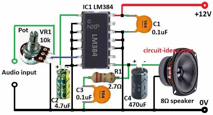
To build a Simple 5W Audio Power Amplifier Circuit follow the connections steps mentioned below:
- First, gather all parts shown in circuit diagram.
- Next, connect pin 1 of LM384 IC1 to ground with capacitor C2.
- After that, connect pins 2, 3, 4, 5, 7, 10, 11 and 12 to ground.
- Then connect pin 6 of LM384 to middle leg of potentiometer of VR1.
- Now connect pin 8 to ground through capacitor C4 and 8Ω speaker, also from pin 8 connect resistor R1 and capacitor C3 to ground.
- Connect capacitor C1 between positive power and ground.
- Finally, pot VR1 first leg connects to audio input, middle leg to pin 6 and third leg to ground.
Conclusion:
Overall, Simple 5W Audio Power Amplifier Circuit using LM384 IC is an useful chip for making small audio amplifiers, also it has features like auto level control, heat safety and easy ground input.
Therefore, always follow safety rules while working with circuits.
Leave a Reply