Simple High Temperature Alarm Circuit using IC 555 uses one special chip called IC 555 which works like a temperature guard; also it keep checking temperature always.
Hence, if its too much hot it make alarm sound like buzzer and tell us something is getting too hot, so we can know early and fix before big problem comes.
Circuit Working:
Parts List:
| Components | Values | Quantity |
|---|---|---|
| Resistors | 10k 1/4 watt | 1 |
| 120k 1/4 watt | 1 | |
| 100Ω 1/4 watt | 1 | |
| Thermistor NTC 10k | 1 | |
| Capacitors | Ceramic 0.1µF | 1 |
| Semiconductors | IC 555 | 1 |
| LEDs Red 5mm 20mA | 1 | |
| Buzzer | 1 |
To begin with, when device get too hot this alarm make beep sound and LED start blinking; also this is simple overheating alarm it watches heat making things like motor or inverter.
Also, it uses small circuit with 555 IC and a low power type.
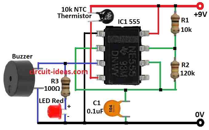
Alarm works when pin 4 reset pin of IC1 get power and this circuit only start when pin 4 goes high, also pin 4 connect to power line through 10k NTC thermistor.
Furthermore, this thermistor has high resistance when it is cold and when it gets hot, its resistance becomes low.
If temperature is normal then thermistor keep pin 4 low and then circuit goes OFF with no sound from the buzzer.
But if temperature goes high and thermistor resistance goes down it gives power to pin 4 and then circuit gets ON and alarm start working.
Note: Keep thermistor close to hot part but in place where it stays quiet when heat is okay.
Formula:
We can make a high temperature alarm using an astable multivibrator with IC 555 and when we set the IC 555 in astable mode, it continuously produces a square wave output.
Also, this square wave can turn ON buzzer or alarm when temperature goes too high.
Frequency (f):
When using IC 555 like astable multivibrator the output frequency is:
f = 1.44 / ((R1 + 2 × R2) × C1)
where:
- f is frequency in hertz Hz
- R1 and R2 are resistors in ohms Ω
- C1 is capacitor in farads F
- 1.44 fixed number from how 555 IC works inside
How formula works:
When IC is in astable mode it keeps making wave up-down like ON-OFF and the values of R1, R2 and C1 decide how fast this wave is.
Important things:
Be sure R1 and R2 are in ohms and C1is in farads, as this formula gives only rough idea of frequency and real frequency can change a bit because of part differences.
Note:
555 IC can work in different ways not just astable.
How to Build:
To build a Simple High Temperature Alarm Circuit using IC 555 follow the below mentioned connections steps:
IC Connections:
- First, pin 1 connects to ground.
- Next, pin 2 connect to pin 6 and also connect small 0.01µF capacitor to ground.
- After that, pin 4 connect to positive side through 10k NTC thermistor.
- Now pin 8 connects to positive power supply.
- Also, LED anode the long leg connects to pin 3 with resistor and LED cathode the short leg connects to ground.
Power Supply:
- Positive wire of power supply connects to pin 8.
- Turn ON the power AND Place NTC thermistor close to hot thing like motor.
- Set its place so alarm start when temperature goes too high.
- When heat goes over set level the alarm will beep and LED will blink.
Adjustment:
- Move thermistor a little until alarm stays OFF when temperature is normal.
Note:
- Before turning ON check all the wires and parts are in right place and correct side.
Conclusion:
This Simple High Temperature Alarm Circuit using IC 555 is easy and useful it use famous 555 timer IC to make alarm sound and blink LED when temperature goes too high.
Also, it work with astable multivibrator setup and NTC thermistor to feel the heat.
Hence, when thermistor feel too much heat it turn ON the 555 IC and then alarm make noise and LED start blinking which indicates us something is getting too hot.
Leave a Reply