To begin with, this Simple Rain Detector Alarm Circuit helps prevent wet clothes during sudden rain by showing you how to build an easy rain detector alarm.
This circuit uses sensor to know when it is going to rain and then it make sound to give warning, so we can take umbrella or bring things inside.
Furthermore, people use similar circuits in car alarms and garden sprinklers and here, we show you how to make a simple rain alarm with only a few parts.
Working Principle:
To make this easy and cheap circuit we need small idea about electronic parts and how circuit work, also, main job of this circuit is to make sound alarm when it feel like rain.
Below we will show how this circuit work:
Circuit Working:
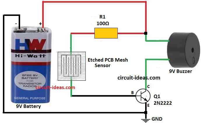
Parts List:
| Components | Values | Qty |
| Resistor | 100Ω 1/4 watt | 1 |
| Semiconductors | Transistor 2N2222 | 1 |
| Buzzer 9V | 1 | |
| Rain Sensor Etched PCB Mesh | 1 | |
| Battery 9V PP3 | 1 |
To start the circuit a small voltage connects to base of 2N2222 transistor.
I built a rain sensor with a wire and Vero board, when rain touches the sensor, the transistor activates.
Next, if the sensor detects rain, the 2N2222 transistor allows current to pass and if there is no rain, the transistor base stays OFF and stops current flow.
As a result, when rain come and touches sensor then alarm turn ON and make sound.
Good and Bad Points:
Good Points:
- This type of circuit is cheap and easy to make as it give sound warning when rain come and so we stay safe
Bad Points:
- Circuit works only for rain not for other weather like wind or snow, as this circuit is not good for big or smart systems
Application and Uses:
Where we can use this Simple Rain Alarm Circuit:
- Farmers can use it to know when rain will start so they can control water for crops.
- Can help save water if we make the circuit better.
- In smart homes this circuit can help close windows or move roof when rain come to protect house.
- In cars it can turn ON wipers when rain or water falls on glass and this will help driver see better in bad weather.
Conclusion:
Easy way to get rain warning on time and avoid surprise problems is by using Simple Rain Detector Alarm Circuit.
Also, this small circuit is helpful in many places like smart homes, farms and cars and anyone can make it but just need little knowledge of electronics.
Further, this rain alarm circuit can make life better whether anyone is a farmer, house owner or person who love cars.
Leave a Reply