Todays time safety is very important, so this Build Your Own Door Knob Touch Alarm Circuit can help protect home and office.
Also, this small project is Door Knob Touch Alarm using 555 IC, which can sense when someone touches the door knob.
Furthermore, if someone touches then alarm makes loud sound and it scares intruder and warn owner or guard; moreover , in this post we can see how circuit work with design parts, formulas and how it is build.
Circuit Working:
Parts List:
| Components | Values | Quantity |
|---|---|---|
| Resistor (All resistors are 1/4 watt) | 100k | 1 |
| 1M | 1 | |
| 100k | 2 | |
| Capacitor | Ceramic 0.01μF | 1 |
| Electrolytic 47μF 16V | 2 | |
| Semiconductors | IC 555 | 1 |
| Transistor BC547 | 1 | |
| Buzzer 9V | 1 | |
| Battery 9V | 1 |
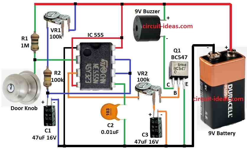
To begin with, this Door Knob Touch Alarm uses an IC 555 in monostable mode, it generates a square pulse when the trigger pin receives an input.
Output time and duty can change by turning VR1 and output from IC 555 goes to VR2 with capacitor C3.
Then it goes to base of transistor Q1 and this make Q1 stay ON for some time and when someone touches door knob then IC 555 start.
Time depend on capacitor and resistor, Q1 get square pulse and turn ON and then buzzer connect to Q1 collector.
When Q1 is ON then buzzer is also ON and alarm sound for short time and we can change time using timing parts.
Also, we can connect relay to IC output to run other electric devices.
Formulas:
Time duration T for 555 timer in monostable mode is:
T = 1.1 × R × C
where:
- R is total resistance for R1 + R2 but in circuit it is VR1 + R2.
- C is capacitor value in farads and in circuit it is C1.
How to Build:
To build a Your Own Door Knob Touch Alarm Circuit follow the below mentioned connections steps:
- First, collect all parts shown in circuit diagram.
- Next, connect pin 1 of IC 555 to GND.
- After that, connect pin 2 between R1 and door knob.
- Then connect pin 3 to middle leg of VR2 and to base of Q1.
- Now connect pin 4 and pin 8 to + supply and then connect pin 5 to GND through C2 capacitor.
- Also, connect pin 6 and pin 7 between R2 and C1 and then put VR1 in series with R2 and C1.
- Further, connect Q1 collector to (+) supply through 9V buzzer and connect Q1 emitter to GND.
- Next, connect middle leg of VR2 to pin 3 of IC 555, connect second leg of VR2 to GND through C3 and then connect third leg of VR2 to base of Q1.
Conclusion:
To conclude, in this post for Build Your Own Door Knob Touch Alarm Circuit with 555 IC is easy and useful for safety purpose.
Also, it works fast when someone touches the knob and we can change circuit as needed if we know how parts work.
Therefore, it is good for small project for students and hobby people to learn electronics.
Leave a Reply