This post show how to make a Alternate Red Green LED Flasher Circuit using red and green LED, it is fun and easy circuit, that is a reason so many people like this project.
Also, this circuit uses two BC547 transistor and they help red and green LED blink one by one.
What is a Alternate Red Green LED Flasher Circuit:
The red and green LED flasher circuit is a small and easy circuit that makes the red and green LEDs blink one after another.
Moreover, people use this circuit for decoration, such as signals or festival lights when red and green flashing is needed.
Circuit Working:
Parts List:
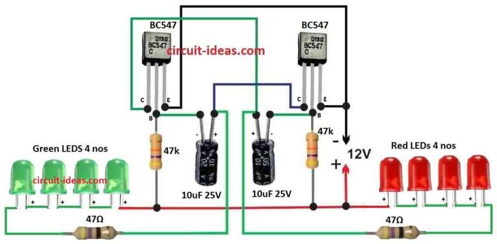
| Components | Values | Quantity |
|---|---|---|
| Resistors | 47k | 2 |
| 47Ω | 2 | |
| Capacitors | Electrolytic 10µF 25V | 2 |
| Semiconductors | Transistor BC547 | 2 |
| LEDs Red and Green 20mA 5mm | 4 each |
This circuit uses BC547 transistor like astable multivibrator which makes square wave signal and this signal connects to LEDs and make them blink one after one.
Here, 10uF capacitor and 47k ohm resistor control how fast LEDs flash and if we change these parts flash speed also changes.
First, the 47 ohm resistor comes in series with the LEDs, so it limits excess current and keeps the LEDs safe, moreover, the red and green LEDs connect in series, so they receive the same current.
Also, LED anodes connects to positive wire and cathodes connects to transistor collector.
Power:
Circuit need 12V DC power to work and we should be sure positive and negative wire connect correct or else parts may get damage.
Testing:
First, when power is ON red and green LEDs start blinking alternately and we can try different resistor or capacitor to make blinking faster or slower.
Formula:
Below is basic formula for astable multivibrator frequency:
Frequency (f):
f = 1 / (1.4 × (R1 + R2) × C)
where:
- f is frequency to how fast it blink
- R1 and R2 are resistors which are both 47k ohm
- C is capacitor with 10uF value
How to Build:
To build a Alternate Red Green LED Flasher Circuit follow the below mentioned steps:
Transistor Connection:
- First, connect emitter of both BC547 transistors to ground of negative side.
- Next, collector of both transistor connects to positive line with 47 ohm resistor in between.
- Also, base of each transistor connects to middle point of one 10uF capacitor and one 47k resistor.
LED Connection:
- After that, put 4 green 5mm LEDs in series with one 47 ohm resistor and connect this to collector of first BC547.
- Also, do the same for 4 red 5mm LEDs in series with 47 ohm resistor and connect to collector of second BC547.
- Then, anodes long leg of both red and green LED strings connects to positive line.
Uses and Application:
- We can use red-green LED flasher for decoration like for festivals, events or home lights, because blinking red and green light look nice and attract people.
- Also, we can use this circuit for signal purpose like alarm system or status display because red and green light can show different state or condition.
Conclusion:
Overall, for people who like electronics making Alternate Red Green LED Flasher Circuit is fun job, as this easy circuit work good for many things like signal or decoration, because it make nice blinking lights.
Further, if we want to change how fast it blink or make it look more cool then we can try using different parts like other resistor or capacitor.
New to this, have an old system 3 volt two button batteries with alternating red & green led’s that no longer function’s. Can system above be modified to provide a 3 volt power source?
Hi mike,
Direct 3V use for this circuit is reliable and will not work good on 3V even if you try to modify, so best use is boost converter circuit (3V → 9V) and then use same circuit without change.
Regards,
sorry is not reliable.