The Rotating LED Array Circuit using IC 555 works like an LED flasher and creates a rotating light effect when we arrange the LEDs correctly, hence, this simple project is easy to build and delivers impressive results.
Furthermore, we can use this circuit for decoration, emergency light or alert and this circuit gives two IC 555 pulse signal and LEDs flash in pattern.
In addition , the circuit runs on small 3V battery and is for low power use.
Circuit Working:
Parts List:
| Components | Values | Quantity |
|---|---|---|
| Resistors (All resistors are 1/4 watt unless specified) | 10k | 1 |
| 150Ω | 1 | |
| 100k | 3 | |
| 10Ω | 12 | |
| Capacitors | Ceramic 10nF | 1 |
| Electrolytic 1µF 25V | 1 | |
| Electrolytic 100µF 25V | 1 | |
| Semiconductors | IC 555 Timer | 2 |
| LED 5mm,20mA any color | 13 | |
| On/Off switch | 1 | |
| Battery 3V | 1 |
To begin with, the circuit use two IC 555 timers and both work as astable multivibrators.
Then IC1 make clock pulse and control first LEDs like LED1 to LED6 which blink steady and then IC2 get signal from IC1 and make different pulse for second LEDs like LED7 to LED12.
IC1 timing and IC2 timing are not same so they blink different.
Capacitor C3 smoothers the voltage and LED13 with resistor 150Ω is always ON as indicator and both timers blink together and make rotating light effect.
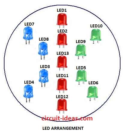
Finally, put LEDs on plastic sheet as shown to get the right effect.
Formulas with Calculations:
The following formulas and calculations explain the Rotating LED Array Circuit using IC 555.
IC1 555 frequency:
f = 1.44 / ((R13 + 2×R14) × C1)
Duty cycle D = (R13 + R14) / (R13 + 2×R14)
R13 = 10kΩ, R14 = 100kΩ, C1 = 1µF
f = 1.44 / ((10k + 200k) × 1µF)
= 1.44 / 0.21
= 6.86 Hz blink about 6 to 7 times per second.
Therefore, IC2 uses same formula with its own R and C values.
How to Build:
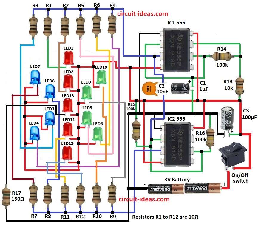
To build a Rotating LED Array Circuit using IC 555 follow below steps for connection:
Connection of IC1:
- First, pin 1 IC1 connect GND.
- Next, pin 2 IC1 connect Pin 6 IC1.
- Then pin 3 IC1 to R1 and LED1 cathode, LED1 anode connect positive and same for R2 to R6 with LED2 to LED6.
- Now pin 4 and pin 8 IC1 connect positive.
- Also, R14 connect between pin 6 and pin 7 IC1 and R13 from pin 7 connect to positive.
- C1 positive connect to pin 2 of IC1 and C1 negative connect to GND.
Connection of IC2:
- First, pin 1 of IC2 connect GND.
- Next, pin 2 of IC2 connect to pin 6 IC2.
- The pin 3 of IC2 connect R7 and LED7 cathode, LED7 anode connect to positive and same goes for R8 to R12 with LED8 to LED12.
- Also, pin 4 and pin 8 IC2 connect to positive.
- Further, R15 from pin 2 IC2 connect to positive and R16 from pin 6 IC2 connect to GND.
- After that, C2 connect between pin 3 IC1 and pin 2 IC2.
- LED13 anode connect to positive and cathode connect to R17 and GND.
- Switch goes between positive of 3V battery and battery negative goes to GND.
- Lastly, C3+ connect to positive and C3 negative connect GND.
Conclusion:
Overall, this post for Rotating LED Array Circuit using IC 555 uses easy two IC 555 chips to make LEDs blink and rotate, also circuit is good for decoration, emergency light and toys.
It works on small battery and looks nice with flashing pattern.
Leave a Reply