The 555 timer chip is very common and easy to use.
It is great for many projects.
But to use it in certain circuits, you need to understand how it works at rest.
There are two important parts to this: the upper threshold pin 6 and the lower threshold pin 2.
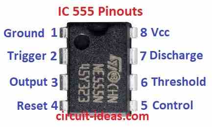
IC 555 Pinouts
Here is a list that shows what each pin on the chip does.
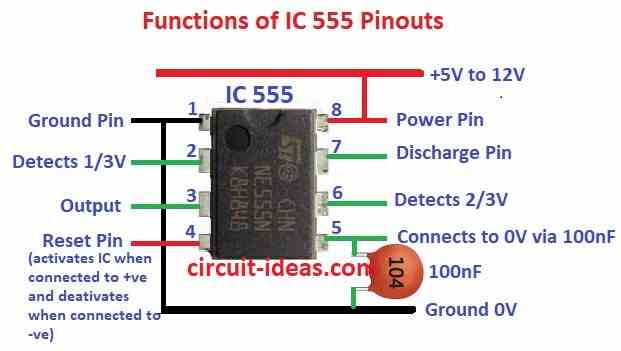
IC 555 Pinouts Functions:
- Draw the 555 timer as a rectangle.
- Label the pins according to their function instead of numbers.
- This will help you remember what each pin does.
IC 555 Internal Structural Layout
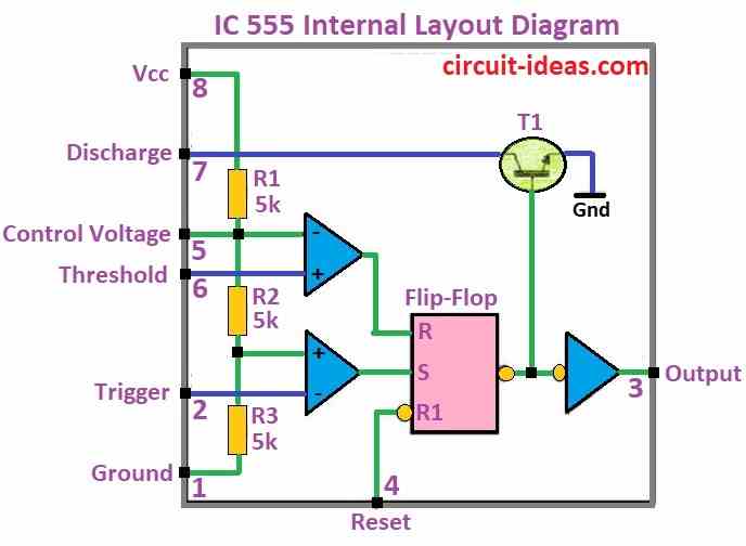
- It can handle power between 16V and 18V.
- Pins 3 output and 7 discharge are connected inside the chip and go low together.
- A resistor R1 pulls pin 7 high.
- The chip can deliver current in two ways:
- It can source current (push it out) up to 100mA at 5V and 200mA at 15V.
- It can sink current (pull it in) up to 50mA at both 5V and 15V.
Here are some common problems you might see with a 555 chip:
- It might use a little more current around 10mA than usual.
- The output voltage might be a bit lower up to 2.5V than the power supply voltage.
- The output voltage might be a bit higher between 0.5 and 1.5V than ground 0V.
- It might source the expected current up to 200mA but only sink half that 50mA.
The 555 timer can be used in different ways to control timing in circuits:
- Astable: This mode makes the chip constantly turn on and off.
- Monostable: This mode makes the chip turn on for a specific time after a trigger signal.
- Voltage Controlled Oscillator VCO: This mode lets you control the on and off timing with a voltage signal.
ASTABLE MULTIVIBRATOR
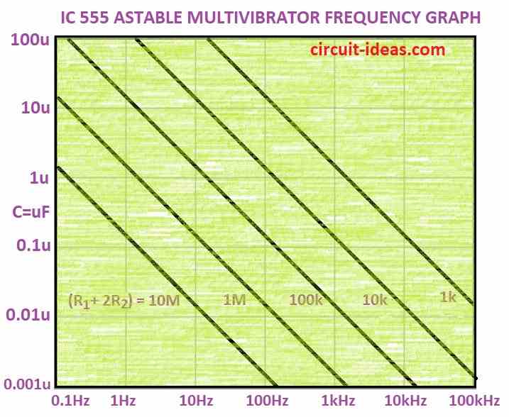
Below is a astable multivibrator frequency graph chart that can help you figure out how fast the 555 chip turns on and off.
The 555 timer chip can work like a flasher turning on and off really fast.
This on off speed called the frequency, can be figured out from this special chart.
Astable IC 555 using graph
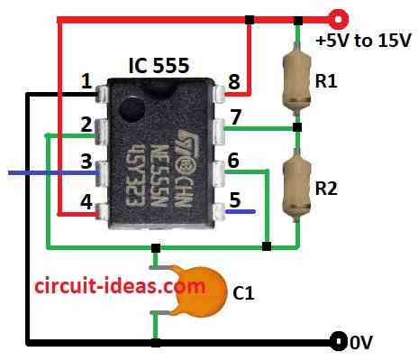
The chart works for circuits wired a specific way.
In this circuit, a capacitor slowly fills up with electricity through two resistors.
When it gets to a certain level a part of the chip pin 6 notices and tells another part pin 7 to discharge the capacitor quickly.
Once empty to a certain point another part of the chip pin 2 notices and tells pin 7 to stop discharging and start filling again.
This cycle keeps repeating.
A small resistor is added to protect the chip from damage.
It does not affect the flashing speed.
Below descriptions is how to use the chart:
- Imagine the two resistors are added together i.e adding 1 hour and 10 hours to get 11 hours.
- The chart scales are tricky, so find a value close to your total resistance on the charts resistor scale e.g.10,000 ohms might be close to a “1” on the 10,000 ohm scale.
- Draw a line straight across the chart from that point.
- Where that line crosses the capacitor value i.e 0.1 microfarad on the charts capacitor scale is your answer the flashing speed in hertz.
Formula:
There is also a formula to calculate the flashing speed, but the chart is a quicker way to get an estimate.
Formula: frequency = 1.4 / [(R1+2R2) x C]
where,
- R1 is the resistance that is linked in series with C.
- The resistance that is linked in parallel to the capacitor C is denoted by R2.
- The capacitance of the capacitor in the circuit is represented by C.
This formula is very helpful for electronic circuits that need to have a blinking or flashing effect, such timer circuits or LED blinkers.
You may modify R1, R2 and C to change the frequency of the blinking or flashing.
IC 555 Astable Frequency table
| 555 astable frequencies | |||
| C | R1 = 1k R2 = 6k8 | R1 = 10k R2 = 68k | R1 = 100k R2 = 680k |
| 0.001µ | 100kHz | 10kHz | 1kHz |
| 0.01µ | 10kHz | 1kHz | 100Hz |
| 0.1µ | 1kHz | 100Hz | 10Hz |
| 1µ | 100Hz | 10Hz | 1Hz |
| 10µ | 10Hz | 1Hz | 0.1Hz |
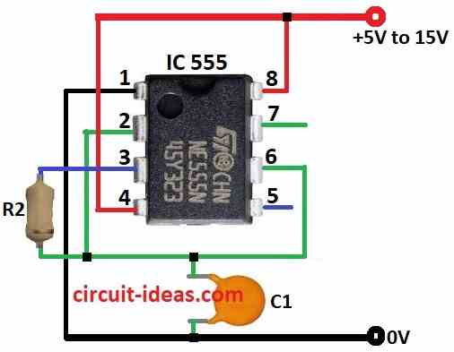
Simple Astable
The most basic 555 timer flasher circuit only needs one resistor and one capacitor.
The chip itself uses pin 3 to both fill up and empty out the capacitor to create the flashing effect.
Formula:
An output of a continuous square wave may be produced by setting the 555 timer integrated circuit in astable mode.
The following formula may be used to determine the oscillation frequency in astable mode:
f = 1.44 (R1+2R2) × C
where,
- The oscillation frequency f is measured in hertz Hz.
- The resistance that connects the 555 timers discharge pin 7 and threshold pin 6 terminals is represented by R1.
- The resistance that connects the 555 timers discharge pin 7 and output pin 3 terminals is represented by R2.
- The capacitance that connects the control voltage pin 5 and ground as well as the discharge pin 7 is represented by the symbol C.
Low Frequency Oscillators
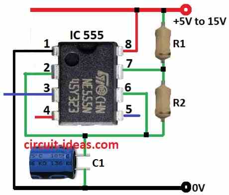
If you swap the regular capacitor for a special type called an ‘electrolytic capacitor,’ the flashing speed frequency will slow way down.
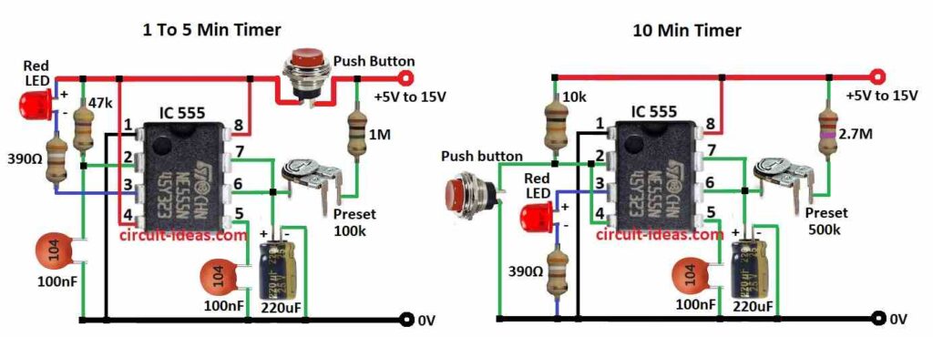
When the flashing gets really slow, less than one flash per second, the circuit is no longer a flasher but a timer or ‘delay circuit.’
The 555 chip can create delays up to 30 minutes this way, but for such long delays the timing accuracy is not perfect.
Low frequency oscillator 555 delay time chart:
| 555 Delay Times: | |||
| C | R1 = 100k R2 = 100k | R1 = 470k R2 = 470k | R1 = 1M R2 = 1M |
| 10µ | 2.2sec | 10sec | 22sec |
| 100µ | 22sec | 100sec | 220sec |
| 470µ | 100sec | 500sec | 1000sec |
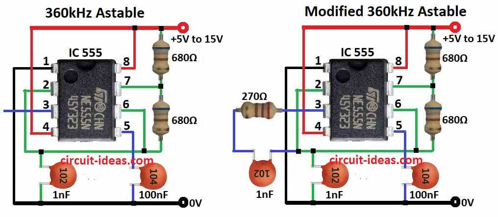
555 ASTABLE OSCILLATORS
The 555 timer chip is a versatile tool!
It can be used to make circuits that flash really fast up to 300,000 times per second (300kHz) or create delays up to 30 minutes.
Keep in mind that super fast flashing speeds might not be reliable, and very long delays may not be perfectly accurate.
SQUARE WAVE OSCILLATOR
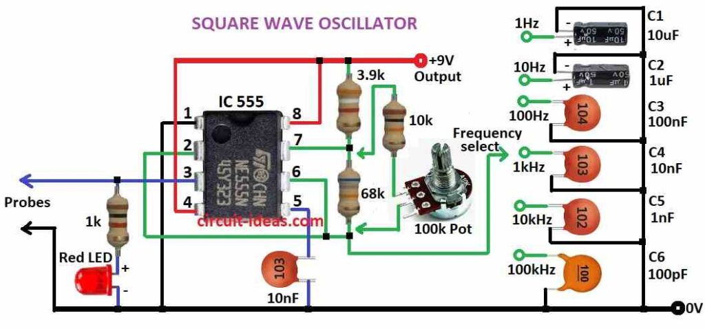
Astable Multivibrator:
In this mode the 555 functions as a free running oscillator continuously generating square wave pulses.
The frequency of these pulses can be controlled by external resistors and capacitors.
Here, the 555 acts as a one shot timer.
An external trigger pulse initiates a precisely timed output pulse of a predetermined duration set by external components.
Bistable Mode:
This mode transforms the 555 timer into a flip flop circuit.
External trigger pulses can toggle the output state high or low similar to a physical switch.
555 Monostable or “one Shot”
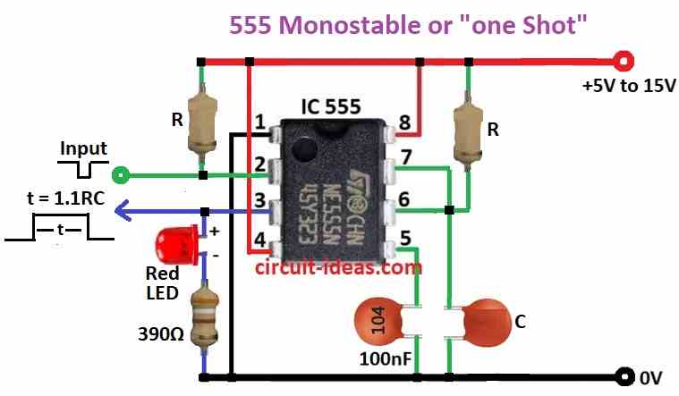
Monostable configuration:
This specific arrangement of resistors, capacitors and connections sets the 555 timer to operate in one shot mode.
Falling edge trigger:
The output voltage transitions to a high state logic 1 only when a negative going voltage pulse falling edge is applied to pin 2 trigger.
Set duration T:
The output remains high for a predetermined time period denoted by ‘T’ after the trigger pulse is received.
This duration is controlled by the values of external resistors and capacitors connected to the timer.
One shot circuit:
This term emphasizes the single output pulse generated by the circuit in response to a single trigger event.
This circuit is also called as a ‘one shot’ circuit.
Conclusion:
Because of its versatility, usability, and extensive application base, the 555 timer integrated circuit (IC) continues to be a mainstay in electronics.
It is still an essential part of electrical design and development, whether it is producing continuous oscillations or exact timing signals.
Leave a Reply