To begin with, Adjustable DC Motor Speed Controller Circuit with Reverse Forward Facility discusses about how to make one simple circuit to control DC motor speed and direction, it uses one popular chip called IC 555 and one special switch.
Hence, we can change motor speed by turning one knob which controls power and send to motor using PWM, also we can make motor go forward or backward by pressing a switch.
Also, this article give some formula to help understand how it work but we should not be number expert to make it.
WARNING: Making circuit with motor can be dangerous, so please do this only if trained person is near and watching.
What is a Adjustable DC Motor Speed Controller Circuit with Reverse Forward Facility:
This circuit controls DC motor speed and also it changes direction from forward to reverse and it uses simple electronic parts so this type of circuit is useful when we need to control motor speed and direction very exact, like in robot or small electric car.
Components Functions:
Firstly, IC 555 makes PWM signal and it works in astable mode, so it gives square wave all the time.
Also, two diodes connect to control how fast timing capacitor charges and discharges and then we can change PWM output by adjusting this.
Additionally, one potentiometer changes charge and discharge time of capacitor and this helps to change PWM duty cycle, so we can control speed of DC motor.
One transistor makes PWM signal strong from IC 555 and it works like a switch to control current going to motor.
How the Circuit Works:
Parts List:
| Components | Values | Quantity |
|---|---|---|
| Resistors | 1k 1/4W CFR | 1 |
| 33Ω 1/4W CFR | 1 | |
| 1W 1Ω | 1 | |
| Potentiometer 47k | 1 | |
| Capacitors | PPC 0.1µF | 1 |
| PPC 0.01µF | 1 | |
| Semiconductors | Diode 1N5402 | 1 |
| Diode 1N4148 | 2 | |
| IC 555 | 1 | |
| Transistor TIP122 | 1 | |
| Switch DPDT 10 amp | 1 |
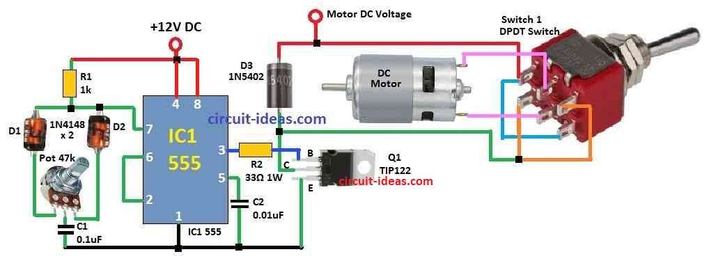
the above circuit, the 555 IC works in astable mode and it makes square wave signal again and again.
Diodes and one potentiometer can change how fast capacitor charges and discharges and this make PWM signal at 555 output pin.
Also, user can turn potentiometer to change duty cycle of PWM and when duty cycle changes, motor speed also changes.
Then PWM signal from 555 connects to base of one transistor and this transistor make signal strong and work like switch for DC motor.
Next, one DPDT switch changes motor direction and when we change switch side, motor goes forward or backward.
Formulas:
f = 1.44 / (R1 + 2 * R2) * C
where:
- R1 and R2 are resistor values
- C is capacitor value
Role of Resistor:
Resistors help make PWM signal, in some circuits resistors do not change duty cycle directly.
But in this formula it can help:
D = R2 / (R1 + 2 * R2)
They change duty cycle and we use PWM with microcontroller, comparator and timers to control duty cycle.
Charge Time (t1) of Capacitor:
t1 = 0.693 * (R1 + R2) * C
where:
- t1 is time to charge capacitor from low to about 63% full
- 0.693 is same like ln(2) which is math constant
- R1 + R2 is total resistor for charging
- C is capacitor in Farad or microfarad µF
Discharge Time (t2) of Capacitor:
t2 = 0.693 * R2 * C
where:
- t2 is time to discharge capacitor from 63% to low voltage
- R2 resistor used during discharge
- C is capacitor value from F or µF
Total Time (T) of One Cycle:
T = t1 + t2
where:
- T is time of full cycle that is from charge + discharge
- t1 is charge time
- t2 is discharge time
This total cycle time depends on values of R1, R2 and C, also this formula is good for simple calculation and for complex circuit we need more advanced method.
How to Build:
To build a Adjustable DC Motor Speed Controller Circuit follow the below mentioned steps:
- First, connect cathode of diode D1 to one side of potentiometer and connect anode of diode D2 to other side of potentiometer.
- Next, connect middle pin of potentiometer to pin 6 of 555 timer.
- And also join the middle pin of potentiometer and where two diodes meet to base of TIP122 NPN transistor.
- Then connect pin 3 of 555 IC to collector of transistor, connect emitter of transistor to ground and connect DC motor to collector of transistor.
DPDT Switch Connection:
- Use DPDT switch to control motor direction.
- Also, connect common terminals of switch to the motor wires.
- One side of other switch terminals connects to transistor collector and other side of switch terminals connects to positive power supply.
Power Supply:
- Connect positive and negative wire of power supply to PCB board and be sure voltage is correct for both motor and IC 555.
Operation:
- Turn the potentiometer to control PWM duty cycle so motor speed changes.
- Also, use DPDT switch to make motor go forward or reverse.
Testing:
- Finally, turn ON the circuit power and watch motor speed and direction change when we turn potentiometer and flip DPDT switch.
Leave a Reply