This Simple Voltage Regulator Circuit using Transistor and Zener work like bodyguard for electricity, because it uses one transistor like door keeper and one special Zener diode to keep voltage not going up-down.
Furthermore, the Zener diode gives fixed voltage and transistor follow that voltage to keep same for our device.
Also, this project is good when voltage goes crazy and makes problem and also transistor can take big power so it is good if our project which need big electric push.
What is a Voltage Regulator Circuit using Transistor and Zener:
A easy way to control and fix power supply voltage is using one transistor and one Zener diode in voltage regulator circuit.
Moreover, power supplies and electronic devices often use this type of circuit when they need a steady voltage.
Circuit Working:
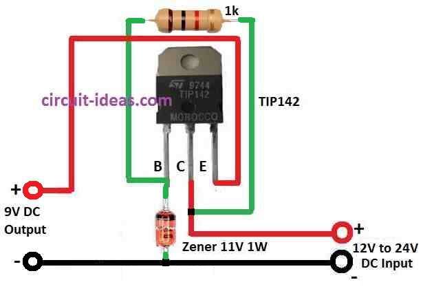
Parts List:
| Components | Values | Quantity |
|---|---|---|
| Resistor | 1k | 1 |
| Semiconductors | Transistor TIP142 | 1 |
| Zener 11V 1W | 1 |
First, this one is Darlington NPN power transistor and it is having two NPN transistors which join together in Darlington way so it gives big current gain.
Then Zener diode uses this like a voltage reference and when voltage reaches Zener level it starts working backward and keep voltage almost same.
Therefore, one resistor connects to the TIP142 base, so it limits excess current from going into the base.
Circuit Operation:
When voltage on Zener diode reaches Zener level it starts working backward (reverse) and start to conduct and we have given 11V DC to power this circuit.
Also, Zener diode connects to base of TIP142 and with this, base of transistor get steady 11V.
Transistor TIP142 work like emitter follower and emitter copy base voltage but little less to around 2V less because of Darlington setup, so this setup gives stable voltage output.
Because the Zener diode keeps the base at 11V, the emitter gives about 11V minus 2V, which is near 9V, therefore, we get a fixed 9V output between the emitter and ground.
Hence, Darlington type make voltage drop near 2V and we count this drop when we find output voltage.
Formulas:
Here, are some easy formula to control DC input voltage to fixed output voltage.
Base Resistor (Rb):
Base resistor (Rb) controls how much current goes in transistor and gives proper bias which uses this formula:
Rb = (Vin – Vz) / Ib
where:
- Vin input voltage like 12V to 24V
- Vz is Zener diode voltage like 11V
- Ib is base current which is around 1mA
Power Loss in Resistor (Rb):
The resistor (Rb) limits excess current from entering the base, so it drops some energy, therefore, use the below formula to calculate it:
Prb = (Vin – Vz)² / Rb
where:
- Prb is power loss in resistor Rb
Remember:
Transistor base emitter voltage (Vbe) is about 0.7V and to make transistor work properly in active zone, Zener diode must get enough current not too much or too low.
So choose right value of Rb and for this check TIP142 datasheet which will tells about transistor gain (β) which help to find better Rb value.
How to Build:
To Build a Simple Voltage Regulator Circuit using Transistor and Zener below mentioned are the connections steps:
- First, TIP142 collector connects to positive supply (Vcc).
- Then, connect the emitter of the TIP142 to the load resistor and then to ground, moreover, calculate the resistor value using ohms law.
- And base of TIP142 connect to anode of Zener diode and also connect to one resistor in series.
- After that, cathode of Zener diode connects to ground and
- Next, load resistor connects between emitter of TIP142 and ground (This is our device or circuit we want to power.)
- Power supply connect to TIP142 collector.
Testing:
- Connect the power supply, then use a multimeter to check the voltage across the load resistor, as it should show around 9V, so this gives a regulated output.
- And if we need different output voltage then change value of base resistor.
Notes:
- Always check TIP142 and Zener diode datasheets for ratings and do not give too high voltage it may break parts.
- Also, if using big power give TIP142 proper heat sink to stay cool.
Conclusion:
In this Simple Voltage Regulator Circuit using Transistor and Zener at TIP142 base Zener diode give steady voltage like reference.
Transistor works like emitter follower so output voltage stay near 9V and does not change too much.
Therefore, Darlington type have big current gain so it is good for circuits that need more current.
Leave a Reply