Think like small switch which controls how much voltage go through.
A normal Zener diode works like a fixed switch that allows electricity to pass only when the voltage rises above a certain level, but this Simple Adjustable Zener Diode Circuit works more like a flexible dimmer switch.
We can also change voltage level using some parts like mostly one thing called potentiometer, as this help us to control how much electricity move in our circuit, as this type of circuits are good for many kind of project.
However, normal Zener diodes are still more common because people do not use adjustable Zener circuits very often.
Circuit Working:
Parts List:
| Components | Values | Quantity |
|---|---|---|
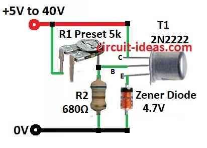
| Resistors | 680Ω 1/4 watt | 1 |
| Preset 5k | 1 | |
| Semiconductors | Transistor 2N2222 | 1 |
| Zener diode 4.7V | 1 |
Adjustable Zener diode circuit works like normal Zener but we can change breakdown voltage from small to big range; also the current going through voltage divider from resistors R1 and R2 must be more than current going to transistor base.
Furthermore, this current come only from R1 and we set it to 8 mA and in this circuit Zener breakdown voltage can change from 5V to 40V.
Circuit keep stable when current is 15 mA and if using Zener with 4.7V and 250mW then the max current will be around 50 mA.
When we want stable voltage more than 15V then better to put heatsink on transistor, as this is important if circuit use 40 to 50 mA current.
Formulas:
This formula help to find output voltage of adjustable zener diode circuit:
Vout = Vz × (1 + R2 / R1)
where:
- Vout is output voltage
- Vz is Zener diode voltage
- R1 and R2 represent resistor values, where R1 connects to the Zener diode and R2 acts as a preset resistor.
We can change output voltage by changing R2 and R1 ratio using the preset and to find maximum output voltage use this formula:
Voutmax = Vz × (1 + R2max / R1)
where:
- Voutmax is max voltage
- R2max is biggest resistance of preset
To find minimum output voltage we can use:
Voutmin = Vz × (1 + R2min / R1)
where:
- Voutmin is lowest voltage
- R2min is smallest resistance of preset
So how high or low voltage goes depends on Zener voltage, resistor R1 and preset values R2max and R2min.
How to Build:
To build a Simple Adjustable Zener Diode Circuit we need to follow the below mentioned steps:
- First, connect one side of preset R1 to positive side of power supply.
- Then connect other side of R1 to base of transistor T1 2N2222 and also to one side of resistor R2 and connect other side of R2 to ground.
- Now connect collector of NPN transistor to positive power supply.
- Also, connect resistor R2 between base and emitter of transistor 2N2222.
- After that, connect Zener diode to emitter of transistor.
- If we want can also connect one capacitor across Zener diode which help for filtering.
Note:
- If voltage goes more than 15V and current reach 40–50 mA then put heatsink on transistor this will stop it from getting too hot.
Conclusion:
To conclude, Simple Adjustable Zener Diode Circuit let us change breakdown voltage of Zener like diode in some range; also this gives us more flexibility for using in voltage reference jobs.
Leave a Reply