Like our previous post on the Low Impedance Input Transistor Preamplifier Circuit, we modify the same circuit to create a medium impedance preamplifier using a BC550C transistor.
Moreover, this circuit increases weak audio signal and we can use it before power amplifier, also it works good for microphone, guitar, or small audio signals.
Furthermore, it gives stable gain and low noise and it also uses few components, so its easy to build.
Circuit Working:
Parts List:
| Components | Values | Quantity |
|---|---|---|
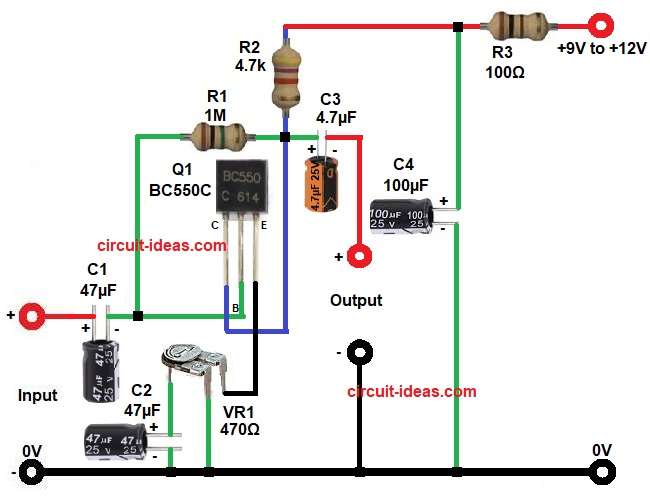
| Resistors (All resistors are 1/4 watt) | 1M, 4.7k, 100Ω | 1 each |
| Preset 470Ω | 1 | |
| Capacitors | Electrolytic 47µF 25V | 2 |
| Electrolytic 4.7µF 25V, 100µF 25V | 1 each | |
| Semiconductors | Transistor BC550C (or BC549) | 1 |
| Power supply +9V to +12V DC | 1 |
First, the circuit uses a 9V power supply, then the supply passes through R3 and C4 and these components reduce noise and make the voltage stable.
After that, the supply goes to the collector of transistor Q1 through resistor R2 and this resistor acts as the collector load.
Also, the base of the transistor needs a small positive voltage compared to the emitter and this voltage is about 0.7V higher than the emitter.
Resistor R1 connects the collector to the base by automatically providing bias, also people call this method self-bias or negative feedback bias and it stabilizes the circuit when the supply changes.
The emitter uses VR1 as a variable resistor to control emitter current and gain and capacitor C2 connects across VR1 to bypass the AC signal and increase the gain.
Also, adjusting VR1 increases or decreases the gain of the amplifier and the circuit takes the output signal from the collector through a coupling capacitor.
Finally, we can also use other transistors like BC549C as these should have high gain (hFE), especially C type for better performance.
How to Build:
To build a Transistor Based Medium Impedance Preamplifier Circuit follow the below connection steps:
- First, collect all the components as shown in the circuit diagram.
- Next, take the BC550C transistor and connect its collector pin to the junction of R1, R2 and the positive end of C3.
- Then connect the base pin to one end of R1 and to the negative side of C1.
- After that connect the emitter pin to the upper pin of VR1 preset and lower pin will go to ground.
- Now connect the input signal to the positive side of C1 and the negative side of C1 goes to the base of the transistor.
- Next, connect R1 between base and collector and connect R2 from collector to Vcc.
- After that connect the negative side of C3 to the output terminal.
- Then connect the positive side of C2 parallel to the middle pin of VR1 and connect its negative to ground.
- Next, connect R3 between Vcc and the circuit supply line.
- Lastly, connect C4 with its positive to Vcc and negative to ground.
Conclusion:
This Transistor Based Medium Impedance Preamplifier Circuit is simple and useful which gives good amplification for small signals.
Moreover, we can adjust gain using VR1, as it uses low cost components and is easy to build.
Also, it works well for audio projects like microphone amplifier or guitar preamp, where we can also modify values for different gain and impedance.
Leave a Reply