This post explains about a Low Impedance Input Transistor Preamplifier Circuit which is designed especially for small audio signals like microphone, guitar pickup and other low level sources.
Also, the circuit uses one NPN transistor BC109C and few resistors and capacitors as it increases the weak signal voltage so next stage amplifier can use it easily.
Further, we have kept the design simple and with low cost, so beginners can build it without difficulty.
Circuit Working:
Parts List:
| Components | Values | Quantity |
|---|---|---|
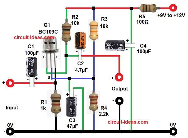
| Resistors (All resistors are 1/4 watt) | 1k, 10k, 18k, 2.2k, 100Ω | 1 each |
| Capacitors | Electrolytic 100µF 25V | 2 |
| Electrolytic 4.7µF 25V, 47µF 25V | 1 each | |
| Semiconductors | Transistor BC109C (or BC548, BC550, BC547) | 1 |
| Power Supply +9V to +12V DC | 1 |
First, input signal is given through capacitor C1 and this capacitor blocks DC and passes only AC signal to the emitter of the transistor.
Then the resistor and capacitor set a fixed bias voltage at the base, so the transistor works in a stable condition.
After that, when input signal comes to emitter, transistor amplifies the signal and we get amplified output from the collector side.
Furthermore, transistor Q1 works as common emitter amplifier and it amplifies the input signal.
Thus, collector resistor R2 and R3 help to set proper voltage gain and operating point.
Also, R3 connects from positive supply to the base of transistor which gives bias voltage to the base and keeps the transistor in active region, so this helps in stable operation of the circuit.
Further, capacitor C2 connects between collector network and output line as it couples the AC signal and blocks DC, so output becomes clean AC signal.
Moreover, resistor R4 controls gain and stability and capacitor C3 bypasses R4 for AC signal, so gain increases at higher frequencies.
After that, R5 works as supply resistor and helps filter noise with C4 and also C4 removes ripple and stabilizes the DC supply.
Finally, we take output from the output point and this signal is stronger than input and ready for next stage.
Note:
If using 9V power supply then R3 should be at 6.8k and if using 12V power supply then R3 should be 12k.
How to Build:
To build a Low Impedance Input Transistor Preamplifier Circuit follow the below steps for connections:
- First, gather all the parts as in circuit diagram above.
- Next, take transistor Q1 emitter pin connect to one side of resistor R1 and one positive end of capacitor C1.
- Then connect collector pin to one end of resistor R2 and one end of capacitor C2 negative.
- After that base pin connect to one end of resistor R4 and positive end of capacitor C3.
- Connect capacitor C1 negative end to INPUT and ground.
- Also, connect capacitor C3 positive end from base of transistor Q1 and negative goes to ground.
- Then connect capacitor C2 negative between collector of Q1 and R2 and C2 positive end goes to positive of OUTPUT.
- After that take R3 and connect one end from positive supply and other end to R4 one end and ground.
- Lastly, connect positive supply through resistor R5 and connect capacitor C4 across supply and ground.
Conclusion:
Overall, this Low Impedance Input Transistor Preamplifier Circuit gives simple and effective amplification for low impedance input signals.
Therefore, with minimum components and easy connections, circuit works well for audio applications like microphone and small signal boosting.
Also, beginners can build this circuit easily and understand transistor amplification clearly.
And if we want higher gain then we can change resistor values or add more stages.
Leave a Reply