Powerful Car Audio Amplifier Circuit using IC TDA2003 are very important and this amplifier make a big difference in car audio; also it make sound signal strong from car stereo.
Furthermore, this power help speaker gives loud and clear sound.
Here, the circuit uses TDA2003 chip and this chip is good, easy to use and gives nice sound and is best for small or medium car audio which gives stereo sound and make music better.
Circuit Working:
Parts List:
| Components | Values | Quantity |
|---|---|---|
| Resistors (All resistors are 1/4 watt unless specified) | 39Ω | 2 |
| 220Ω | 2 | |
| 2.2Ω | 2 | |
| 1Ω | 2 | |
| Capacitors | Ceramic 39nF | 2 |
| Ceramic 100nF | 4 | |
| Electrolytic 100μF 25V | 2 | |
| Electrolytic 470μF 25V | 2 | |
| Electrolytic 1000μF 25V | 2 | |
| Electrolytic 10μF 25V | 2 | |
| Semiconductors | IC TDA2003 | 2 |
| Heatsink IC TDA2003 | 1 | |
| ON / OFF Switch | 1 | |
| Fuse 2A | 1 | |
| 4Ω Speakers | 2 |
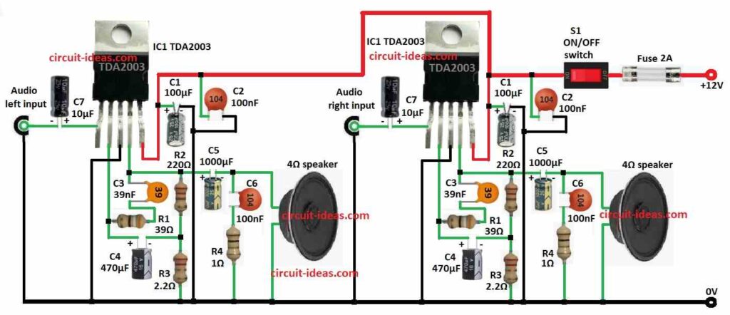
Circuit diagram show two same channels for stereo sound and each uses TDA2003 IC and each channel has parts like resistor, capacitor and speaker and all work together to make sound.
Also, it uses 12V DC power which is common in cars.
Here, TDA2003 is main chip and it drives low ohm speaker like 4 ohm with low distortion and then audio signal goes to pin 1 of non-inverting input through capacitor C7 and this blocks the DC.
Resistors R1 and R2 set gain and control how much the signal is boosted.
After that, capacitor C1 and C2 clean power, reduce ripple and make circuit work smooth and then capacitor C6 keep frequency stable and stops bad oscillation.
Now amplified signal come out from pin 4 and goes to speaker through capacitor C5 and this block DC and pass AC signal.
Finally, 2A fuse protect circuit and speaker from too much current and use heatsink on TDA2003 to keep it cool.
Formulas with Calculations:
Use these formulas to help design strong car amplifier with TDA2003 IC:
Voltage Gain (Av):
Av = 1 + (R2 / R1)
where,
- R1 is 39 ohms
- R2 is 220 ohms
Av = 1 + (220 / 39) = 6.64
Signal become 6.64 times bigger.
Output Power (Pout):
Pout = (Vsupply²) / (2 × Rload)
where,
- Vsupply is 12V
- Rload is 4 ohms
Pout = (12²) / (2 × 4) = 18W
Each channel gives around 18W power.
Capacitor C4 is for low frequency pass:
fc = 1 / (2 × π × Rload × C4)
where,
- Rload is 4 ohms
- C4 is 470μF
fc = 1 / (2 × 3.14 × 4 × 470 × 10⁻⁶) = 85 Hz
Hence, frequencies above 85 Hz goes to speaker.
How to Build:
To build a Powerful Car Audio Amplifier Circuit using IC TDA2003 follow the below mentioned steps for connections:
- First, put all parts as shown in circuit diagram.
- Next, connect pin 1 of IC1 TDA2003 to left audio input and GND using capacitor C7.
- Then connect pin 2 to pin 4 through capacitor C3 and resistor R1 in series and also connect capacitor C4 from pin 2 to between resistor R2 and R3.
- Now connect pin 3 to GND and then connect pin 4 to one end of 4Ω speaker using capacitor C5 and other end of speaker goes to GND.
- After that, connect R2 and R3 in series from pin 4 to GND and add capacitor C6 and resistor R4 from pin 4 after C5 to GND.
- Also, connect pin 5 to +12V power using capacitors C1 and C2 in series and also connect to GND.
- Further, add ON/OFF switch and fuse 2A in series on +12V line and do same steps again for the right channel to make the stereo.
Conclusion:
Overall, this Powerful Car Audio Amplifier Circuit using IC TDA2003 is simple but strong, as it give good sound, low distortion and is great for cars.
Also, it us modular and is easy to change for other speakers and if we build it carefully and test it right then we can boost our car sound a lot!
Leave a Reply