This article for Self Discharge Battery Protection Circuit teaches how to make one easy circuit to protect car battery (lead acid type) when not using.
Also, this circuit help battery live more long time and keeps it healthy.
WARNING: Making lead battery for car can be dangerous, so try to do this with one big person who know how to work safe with car battery.
Circuit Working:
Parts List:
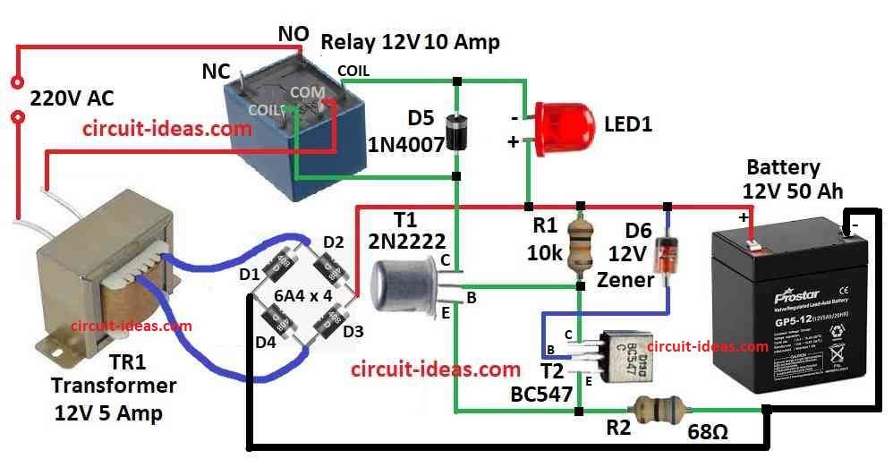
| Components | Values | Quantity |
|---|---|---|
| Resistors | 10k, 68Ω (1/4 watt) | 1 each |
| Semiconductors | Diode 6A4 | 4 |
| Diode 1N4007 | 1 | |
| Zener Diode 12V 1 watt | 1 | |
| Transistors BC547, 2N2222 | 1 each | |
| LED 5mm 20 mA | 1 | |
| Relay 12V 10 Amp | 1 | |
| Transformer 12V 5 Amp | 1 |
This circuit is very good for saving lead acid battery when not in use for long time but still need to work; also it gives small charge to battery and let battery discharge slowly by itself and by circuit.
Also in this circuit, battery charge goes down and charger starts again by itself and when it reaches special charge level (SoC).
Moreover, in circuit Schmitt trigger T1, T2, diode and Zener diode D6 help to set SoC level to stop charger and also resistor R2 gives needed hysteresis.
Here, the circuit uses steady power voltage to test the relay and check if the relay works without main power and without battery plug.
Hence, set battery voltage between 13.6V and 12.5V to make this self discharge protect circuit working good and also to make ON point more correct add 1N4148 diode with D6.
Then to change OFF point try to change R2 resistor maybe use 100 ohm, we can also use battery charger instead of bridge rectifier and transformer.
But be careful if battery is very low below 10V then ,it does not work because relay does not starts, for that first charge battery to more than 10V and then connect to circuit.
We can also add one switch with relay to turn OFF main power and if want to protect two 12V battery then we can make coil voltage, D6 Zener voltage and transformer voltage double.
Use fuse to protect all parts from short circuit and connect two battery in series to terminal and also put 1A fuse to protect transformer side, hence there is no need for smoothing capacitor here battery does that job.
Formula:
Below is formula for Self Discharge Battery:
Self discharge current = mAh / current
here,
Self discharge current show how much battery loses power by itself and it is in mA (milliampere) or µA (microampere) this happen because of battery chemical inside.
mAh (milliampere hour) means battery is full power and how long it can give current.
More explain:
Self discharge is percent loss per month, for example 3% per month for lithium battery which mean battery loses 3% even not in use.
Battery company datasheet show this information, for example battery of 1000 mAh with 3% per month, even if there is no use of battery to lose 30 mAh in one month.
How to Build:
To build a Simple Self Discharge Battery Protection Circuit following are the below mentioned steps for connection:
Collect parts:
- First, take all parts listed above and use circuit diagram to know what we need.
Understand diagram:
- Next, look carefully at circuit diagram it shows how to join parts and where to put each one.
Connect transformer and bridge rectifier:
- After that, join transformer and bridge rectifier same like in diagram and be sure wires and polarity are correct.
Join Zener diode and resistor:
- Now connect R2 resistor and Zener diode D6 like in diagram and we can change R2 value if needed or use 100 ohm preset for easy setting.
Add Schmitt Trigger T1 and T2:
- Then put Schmitt trigger parts T1, T2 and Zener in place as in diagram.
Add 1N4148 diode:
- Also, to fix ON voltage correct, join 1N4148 diode in series with D6.
Connect relay:
- Before add relay to board and check its coil pins are right.
Optional switch:
- If we use a switch to turn OFF power then connect it in parallel with relay contact.
Fuse protection:
- To stop short circuit use fuse and put 1A fuse in transformer main line to protect it.
Connect battery:
- Join batteries to circuit in series across terminals.
Testing time:
- Before using battery test circuit with regulated power supply and see if relay goes ON and OFF as it should.
Make changes:
- Set voltage between 13.6V and 12.5V to test ON/OFF and change ON/OFF values if needed.
Be safe:
- Always be careful with electric parts and follow safety rules and ask help from expert or person who knows.
Conclusion:
To conclude, Self Discharge Battery Protection Circuit helps battery from losing power slowly when not used for long time.
Also, this circuit protects battery life and keeps battery in good condition, therefore many battery operated devices and backup systems use this circuit.
Leave a Reply