This article teaches us How to Build a Simple LED Circuit; an LED is small special light that shine when to get electricity.
Also, this project show how to join some parts together to make LED turn ON.
Moreover, people use LED circuits in many things like torch lights, car back lights and even big signboards.
Circuit Working:
Parts List:
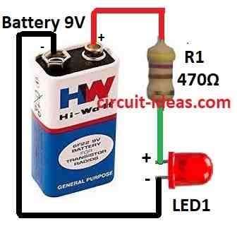
How to Connect LED with Battery Circuit:
Here, we explain some examples of LED circuits like blinking LED 220V LED and more.
First, we will show simple LED circuit with one resistor in series how it works; also to choose correct resistor one must do small math to know the following:
- Battery voltage (power supply)
- LED voltage drop (usually around 2V)
- How much current one want (like 10mA or 20mA)
With this one can find good resistor value so LED works safe and does not burn.
Formula and calculations for a series LED circuit :
Source Voltage−LED Voltage Drop/Amps = Ohms
where:
Amps = mA/1000
For instance: Source Voltage = 9V
LED Voltage Drop = 3.1V typical for a blue or white LED
Desired Current = 13 milliamps
So, we calculate the needed resistor as: (9 − 3.1) / (13/1000) = 452Ω
Thus, we used 470Ω resistor.
How to Build:
Steps to build a simple LED circuit with resistor in series are shown below:
Find Resistor Value:
- First, check how much voltage the LED is using (forward voltage).
- Then one must know the battery or power supply voltage.
- Also, choose how much current one want for LED (like 20mA).
- Use Ohms Law: V = I × R so R = (Supply Voltage − LED Voltage) ÷ Current
- After that, take resistor value close or little higher to keep LED safe.
Connect the Parts:
- Put LED and resistor on breadboard or get ready for solder.
- Now connect short leg cathode of LED to negative (-) of battery and connect long leg anode of LED to one leg of resistor.
- Also, the other leg of resistor go to positive (+) of battery.
- Be sure all wires tight and no short circuit.
Test the Circuit:
- Turn ON the power and check if the LED glows properly, also use a multimeter to check the current and see if it matches the required value.
Fix Brightness if Needed:
- If LED is too bright or not bright than change resistor value.
Final Test:
- Last check to see if LED work perfect in the project.
Note:
- By following these steps one can make simple LED circuit with resistor; but be careful while working with electric parts and always check twice with wires and math.
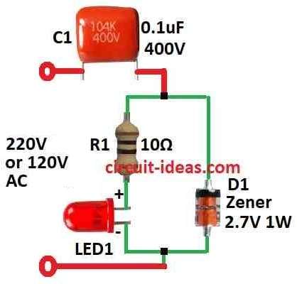
How to Build a 220V LED circuit:
A 220V LED circuit uses some electrical parts to make LED work with 220V power.
People use this kind of circuit in places where power plugs give 220V, like in some countries with high voltage supply.
Circuit Working:
Parts List:
| Components | Quantity |
|---|---|
| Resistor | |
| 10Ω 1/4 watt | 1 |
| Capacitor | |
| PPC 0.1µF 400V | 1 |
| Semiconductors | |
| LED any 5mm 20mA | 1 |
| Zener Diode 2.7V 1W | 1 |
LED Circuit Work on 220V Warning!:
Do this only if anyone knows good about electronic stuff, as this circuit connect direct to 220V power, which is very dangerous and can give big shock.
Also, this circuit uses parts like one capacitor, one Zener diode, one resistor and LED.
How big the capacitor is will decide how much current will LED need; for example 0.1 microfarad (µF) capacitor give around 4 mA to LED.
If use 470 nano farad (nF) then LED get about 20 mA.
How to Build:
To build a Simple LED Circuit one need to know the working with 220V is very risky; so one must handle with care and follow safety rules.
Building the Plan:
- First, decide how much current one needs for an LED to choose capacitor and other parts for that.
- Also, look at some diagram or guide to know how to put parts in right way.
Safety First:
- Be sure power is OFF and unplug before anyone touches anything and use tools with plastic handle and do not touch wires with bare hand.
- Work in place with fresh air and alway follow safety rule.
Connect the Parts:
- Put all parts like in diagram and be careful with direction of diode and capacitor that they wont work if it is wrong side.
- Use wire with cover (insulated) for join parts and check everything again and check for no loose wire or short circuit.
Test the Circuit:
- After connecting everything, now plug in power and check if LED turns ON and it should glow.
- Use meter to check how much current is going it should match as per needed
Fix Problems:
- If LED is not flashing or something strange happen than turn OFF and unplug quickly; also check again for all wire or maybe something wrong or broken.
- Change broken parts or fix wire then try again.
Finish the Job:
- When all parts are working fine keep all parts tight and safe and cover any open wire or metal with tape or insulator.
- Write down some notes like what capacitor used or how much current.
Final Safety Check:
- Check again that all parts are strong and no open wire remains and also run the circuit for some time and see if it stays safe.
Note:
- This is not small project it operates on 220V that can hurt or kill; so if one do not know much about electronics better ask help from a trained person but do not try alone.
Conclusion:
To conclude, this How to Build a Simple LED Circuit overall give useful and low power way to make light in many kinds of electronic things and system.
Leave a Reply