This simple flasher circuit uses an LED and an LDR to create the flashing effect; as the light level changes, the LDR changes its resistance, which controls the LEDs blinking.
Hence, there is no need for big chips or transistors but still the LED blink happens, also it uses simple parts like resistor, capacitor and special light sensor called LDR.
Circuit Working:
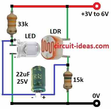
Parts List:
| Components | Values | Quantity |
|---|---|---|
| Resistors | 33k 1/4 watt | 1 |
| 15k 1/4 watt | 1 | |
| Sensors LDR (Light Dependent Resistor) | 1 | |
| Capacitors | Electrolytic 22μF 25V | 1 |
| Semiconductors | White LED 5mm 20mA | 1 |
LED and LDR work like team and LED gives light to LDR and this light make LDR resistance go down AND Then more current flow.
Then more current make LED brighter and bright LED gives more light to LDR, so LDR resist even less and LED get even brighter; but not forever one capacitor store energy like battery.
When LED is ON capacitor fill up and when full LED stop with no more energy.
LED OFF means LDR get less light and so LDR resistance goes up and then capacitor gives back power slowly.
LED gets little bright again and LDR get light again and loses resistance again with LED blink starts again; like see-saw, LED up and LDR down.
Furthermore, capacitor work like timer and stop LED when too bright and then LED start again when capacitor release energy and then blink repeats.
Tips for better blink:
- Use bright LED near LDR which work best in low light with too much light stops blink and LDR is too conductive.
- We can also, use adapter or small battery.
- Very simple but fun circuit with few parts make nice blinking effect.
Formulas:
With just resistor and capacitor we can make LED and LDR flasher circuit.
Here is simple formula:
We can calculate the LED blinking frequency using the RC time constant:
f = 1 / (2.2 × R × C)
where:
- R is the resistance in ohms Ω
- C is the capacitance in farads F
This formula help to guess how fast LED will blink by using resistor and capacitor values.
How to Build:
To build a Simple Flasher Circuit using LED and LDR follow the below mentioned steps for connections:
- First, take all parts as shown in circuit diagram.
- Next, connect LED anode to positive (+) with 33k resistor and connect LED cathode to ground (-).
- Then connect one leg of LDR to positive (+) and connect other leg of LDR to ground (-) through 15k resistor.
- After that, connect anode of 22μF capacitor between LDR and 15k resistor and then connect cathode of 22μF capacitor between LED anode and 33k resistor.
Conclusion:
To conclude, this Simple Flasher Circuit using LED and LDR shows how simple parts make blinking light; by using LED, LDR, resistors and capacitor through this smart way we can get auto blinking effect.
Also, it is good small project and helps to learn about light sensor and make more big electronic ideas.
Leave a Reply