To begin with, this article talk about two main parts for wireless phone charging:
- Transmitter circuit
- Receiver circuit.
So, making Simple Wireless Mobile Phone Charging Circuit is easy and for that we only need resistors, capacitors, diodes, voltage regulator, copper coils and transformer to make circuit work good.
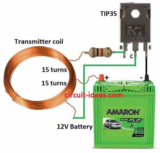
Transmitter Circuit Working:
Parts List:
| Components | Values | Quantity |
|---|---|---|
| Resistor | 1k 1/4 watt | 1 |
| Semiconductors | Transistor TIP35 | 1 |
| Transmitter coil (30 turns, center tap, 0.5mm super enameled copper wire, 18 cm diameter) | 1 | |
| Battery 12V | 1 |
Power Source and Coil Setup:
First, a coil connect to 12V battery which gives power to circuit and this coil then connect with transistor TIP35 and capacitor C.
Transmitter Working:
An oscillator circuit make AC current in transmitter coil and this AC current create magnetic field around coil.
When the receiver coil comes close to the transmitter coil, inductive coupling creates a voltage in the receiver coil.
Next, the receiver circuit converts the AC voltage to DC and then it charges the battery.
How Inductor Works:
Center tapped inductor:
Furthermore, one inductor cuts in middle makes two equal parts but still magnetically connected, which help to make two inductors from one.
Oscillator Circuit:
The transistor and other components repeatedly generate an AC signal (oscillate); for this purpose, designers commonly use two types of center-tapped inductors.
1. Hartley Oscillator:
DC power connect to center of inductor and capacitor, transistor base and collector connect to sides of inductor; together they create feedback loop to keep signal oscillating.
How Transmitter Coil Works:
DC power goes into circuit and transistor and inductor make current oscillate, as both halves of inductor get this current.
Furthermore, one half makes opposite voltage in other half using magnetic coupling and this create strong AC voltage in whole inductor.
Also, transmitter coil sends this AC voltage as magnetic field.
Advantages of Center Tapped Inductor:
No need for two separate inductors which makes circuit easier which is more efficient than using two inductor, so allows DC current for transistor without disturbing AC signal.
Important Points:
Need some electronics knowledge and right parts to build circuit safely.
Frequency of oscillation is important because it must match the receiver.
In addition, the charger needs safety features such as object detection and heat protection and furthermore, proper coil placement plays a crucial role in achieving efficient charging.
Coil Placement:
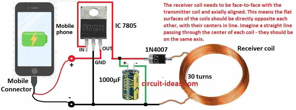
Alignment:
Coils should face each other and centers of coils should line up on same axis.
Distance:
Coils should be close with best gap is 1 to 10 mm as more gap means less power.
Overlap Area:
Bigger overlap between coils means better efficiency as bigger transmitter coil helps if receiver coil is small.
Misalignment Tolerance:
Perfect alignment not always possible, rectangular coils gives more tolerance than round ones and some advanced chargers use many coils or special shapes to help.
Receiver Circuit Working:
Parts List:
| Components | Values | Quantity |
|---|---|---|
| Capacitor | Electrolytic 1000μF 25V | 1 |
| Semiconductors | IC LM7805 | 1 |
| Diode 1N4007 | 1 | |
| Mobile phone | 1 | |
| Mobile connector | 1 | |
| Receiver coil (30 turns, 0.5mm super enameled copper wire, 18 cm diameter) | 1 |
Receiver Circuit Working:
Receiver coil get small AC voltage from transmitters magnetic field, diode 1N4007 change AC to pulsing DC and capacitor 1000 μF smooth the pulsing DC to steady voltage.
Better Charging with Voltage Regulator:
7805 Voltage Regulator make stable 5V output from capacitor voltage and this safe 5V protect phone battery from bad voltage changes.
Also, 7805 fix big problem in old design with no stable voltage and with 7805 IC circuit is more safe and useful; but for real safety better use good commercial chargers with more safety features.
Formulas:
Formula for Output Voltage:
To get final DC voltage from receiver circuit:
Vout = Vpeak − Vdiode − Vdropout
where:
- Vpeak is the peak AC voltage from receiver coil
- Vdiode is the diode voltage drop from 0.7V for 1N4007
- Vdropout the voltage lost in 7805 IC with 2V
This formula helps understand how to design basic receiver circuit and this circuit may need changes based on our needs.
Safety Warning:
- Remember! Commercial wireless charger manufacturers test their products for safety and therefore, do not build your own charger unless we have a good understanding of electronics, as doing so can be risky.
Conclusion:
To conclude, Simple Wireless Mobile Phone Charging Circuit is easy and has no wires, as it works using inductive coupling.
Moreover, transmitter coil makes AC magnetic field and receiver coil picks up magnetic field and turns it into DC to charge phone battery.
Leave a Reply