To begin with, this Simple Heat Sensor Circuit using a Single Transistor and one special resistor like thermometer.
When it get hot this resistor changes to how it work because of which the transistor sees this change; also the transistor work like a door and if temperature changes it opens or closes for electric.
So the circuit can detect when something is too hot.
Circuit Working:
Parts List:
| Components | Quantity |
|---|---|
| Resistors (All resistors are 1/4 watt) | |
| 1k | 1 |
| 470Ω | 2 |
| Preset | 1 |
| Thermistor NTC 4.7k | 1 |
| Semiconductors | |
| Transistor BC547 | 1 |
| LED any 5mm 20mA | 1 |
| Buzzer | 1 |
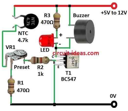
This circuit uses a BC547 transistor as a common-emitter amplifier and the transistor base connects to the middle pin of the preset resistor.
Also, emitter connects to the ground and collector connects to LED with 470 ohm resistor in series.
Then two side pins of preset resistor connects one side with 4.7k NTC thermistor and other side connects to ground; also preset resistor help to set heat limit point.
Furthermore, NTC thermistor work like heat sensor when temperature go over set point and it turns ON BC547 transistor.
Then LED and buzzer turns ON and indicates that temperature is too high, also the circuit work with 12V DC power.
Formulas:
An NTC thermistor serves as a heat sensor in many circuits to detect temperature changes, also it is a special type of resistor whose resistance decreases as the temperature increases.
Hence, this makes it good for checking temperature.
Steinhart Hart Formula:
This formula help to know temperature from thermistor:
1 / T = A + Bln(R) + C(ln(R))3
where:
- T is temperature in Kelvin (K)
- R is resistance of thermistor at that temperature
- A, B, C are values from thermistor datasheet
Simple version of formula also look like:
T = 1 / A+Bln(R) + C(ln(R))3
where;
- T is temperature
- R is resistance and
- A, B, C are numbers from datasheet.
Note:
To get correct temperature use right A, B, C from the thermistor datasheet., also sometimes calibration needed to make it more accurate.
Using this formula with real values the NTC thermistor can work good as temperature sensor; but just change the resistance into temperature using this method.
How to Build:
To build a Simple Heat Sensor Circuit using a Single Transistor we need to follow the below mentioned steps:
Circuit Design:
- First, connect middle pin of preset resistor to base of BC547 transistor.
- Then connect emitter of transistor to ground and connect collector of transistor to long leg anode of LED and short leg cathode of LED connects to one side of 470 ohm resistor.
- Also, other side of resistor connects to positive side of power source of 12V DC.
- One side pin of preset resistor connect to 4.7k NTC thermistor and other side pin of preset resistor connects to ground.
Set Temperature Limit:
- Turn preset resistor to set how hot it should be before LED and buzzer turn ON, turning it change voltage on transistor base so circuit turn ON at different temperature.
- Give 12V DC power to circuit and then watch LED and buzzer as they should turn ON when it gets hot enough.
- If not right then turn preset resistor more to adjust.
Final Step:
- Ensure all wires and components are securely fixed and label the circuit for future reference.
Note:
- Also, by following these steps, we can make the heat sensor circuit work properly.
- Handle the wires and components carefully and ensure we connect everything correctly to maintain safety.
Conclusion:
To conclude, this Simple Heat Sensor Circuit using a Single Transistor and one thermistor works simple and good to check temperature change.
Because thermistor change with heat and transistor can make signal stronger this small circuit can show temperature change with LED or buzzer; also it easy to build so it is good for students, hobby people or small projects where one needs to watch a heat.
Lastly, one can change parts or adjust preset to make it work for different heat levels.
Leave a Reply