This is an Easy and Simple Magnetic Field Sensor Circuit, which can find magnet near the sensor.
Furthermore, this circuit is easy to make and is good for beginners, where we can learn how it work and also we can use in small projects which are very fun and useful!
What is a Magnetic Field Sensor:
A magnetic field sensor circuit is used to detect and measure the strength of a magnetic field around it, also it mainly uses a hall effect sensor, which generates a voltage depending on the strength and direction of the magnetic field.
Hence, these circuits are used in compass, robots, machines and cars also.
Circuit Working:
Parts List:
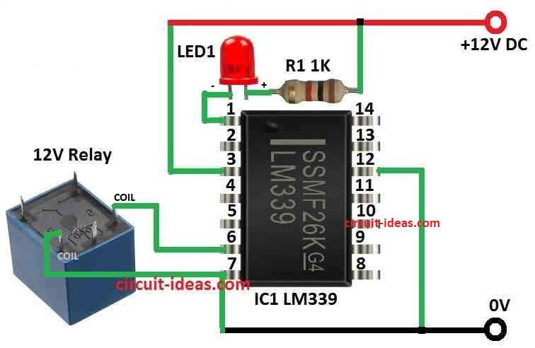
To begin with, this smart circuit make magnetic field sensor using relay coil instead of normal meter like before, where we can feel small changes in magnetic field very well.
LED1 light turns ON when small magnet comes near the relay coil.
Also, this sensor works same like old one with moving coil meter but now coil is fixed and magnet moves.
Here, we can also use any relay coil but best one is with high resistance and big inductance like 400 ohms.
Furthermore, if we keep a magnet few inches from the coil side by side it can also sense iron things moving between coil and magnet.
Also, when magnetic field changes small AC voltage comes in coil and op-amp makes this small signal bigger and LED1 becomes bright or dim.
Lastly, just follow the making steps to understand this sensor better.
Formulas:
A Simple Magnetic Field Sensor Circuit is made using these easy formulas:
Magnetic Flux (Φ):
Φ = B * A * cos(θ)
- B is power of magnetic field.
- A is coil area of cross section.
- θ is angle between coil and magnetic field.
Induced EMF (ε):
ε = −N * ΔΦ / Δt
- N is how many turns in the coil.
- ΔΦ is change in magnetic flux.
- Δt is change in time.
Resistance (R) ohms law:
V = I * R
- V is voltage across coil.
- I is how much current is in coil.
- R is coil resistance.
How the Circuit is Build:
Below are the connection steps, for how to Make Simple Magnetic Field Sensor Circuit.
- First, choose a relay coil with high inductance and around 400 ohms resistance.
- Next, collect all parts like op-amp, resistors, capacitors and LED.
- Then use the relay coil instead of normal meter in circuit.
- After that, connect relay coil with op-amp, resistors, capacitors and other parts.
- Also, keep a small magnet few inches from relay coil side by side which is parallel to coil pole.
- Finally, give right voltage to circuit and be sure all parts are correct.
Testing:
- Move small magnet slowly near the coil and through this LED1 should turn ON.
- After that, put iron piece between magnet and coil and watch LED1 to see if it changes when magnetic field changes.
Conclusion:
Overall, this Simple Magnetic Field Sensor Circuit is simple and can feel even small changes in magnetic field.
Also, it is useful in many areas like science, machines and learning electronics.
Leave a Reply