• Skip to primary navigation
  • Skip to main content
  • Skip to primary sidebar

Circuit Ideas for You

Get free circuit ideas online.

  • Home
  • Privacy Policy
  • About
Home » Simple Transistor Relay Driver Circuit

Simple Transistor Relay Driver Circuit

Last updated on 28 April 2025 by Admin-Lavi Leave a Comment

Small switches called transistors are found in almost every electronic device.

However they are unable to manage an abundance of power alone.

A transistor relay driver is similar to a specialized transistor adapter.

It enables the control of a strong relay switch by a tiny transistor signal.

This makes it possible to turn on and off power hungry devices like lights and motors using a little weak signal from the circuit.

This is a important idea to understand before beginning any electronics project.

What is a Transistor Relay Driver Circuit:

A circuit that controls a relays operation using a transistor is known as a transistor relay driver circuit.

Electromechanical switches known as relays are used to regulate circuits or devices with high power using a low power input.

The relay coil is motivated by a low power signal that is increased by the transistor in the relay driver circuit

Circuit Working:

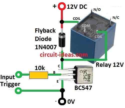
Simple Transistor Relay Driver Circuit Diagram

Parts List:

TypeSpecificationQuantity
Resistors10k1
SemiconductorsTransistor BC5471
Flyback Diode 1N40071
Relay 12V1

Transistors reach an active state when a little voltage exceeding 0.6V is put across their base-emitter junction.

Because it permits the transistor to flow current between its collector and emitter terminals this activation is essential.

The activated transistor serves as a switch for the relay.

With the transistor conducting current flows through the relay coil.

The magnetic field generated by this current causes the relays internal switch to close allowing a larger load to be connected or disconnected.

The relay coil experiences a reverse electromotive force (EMF) when the relay is deactivated or the input voltage is removed.

To avoid this back EMF from harming the transistor a route for its circulation is provided by the freewheeling diode connected in parallel with the relay coil.

It ensures a safe discharge path for the stored energy in the relay coil.

To regulate the current entering the transistors base a base resistor is added.

To maintain the transistor in its active zone without overloading it the base current must be set properly.

This information is necessary to find out component sizes and ensure that the relay operates within the parameters that have been set.

Formulas and Calculations:

Here we will calculate the base resistor value (Rb) for a current limiter circuit using a BJT transistor.

    Vin = (Vs – 0.7) * HFe / Collector Current

    where,

    • Vin is the base voltage of the transistor usually in the range of 0.7V to 1.2V
    • Vs is the supply voltage of the circuit
    • HFe is the DC current gain of the transistor
    • Collector Current is the desired maximum current allowed through the collector

    Steps to calculate Rb:

    Rearrange the formula to solve for Rb:

      Rb = (Vs – Vin) / (HFe * Collector Current)

      Calculate Rb:

      Rb = (Vs – Vin) / (HFe * Collector Current)

      Rb = (12V – 0.7V) / (100 * 0.01A)

      Rb = (11.3V) / (1mA)

      Rb = 11300Ω = 11.3 kΩ

      Note:

      The resultant value of 11.3 kΩ is in close agreement with the given value of 10 kΩ.

      This indicates that expected given HFe value of 100 the selected base voltage of 0.7V and collector current of 10mA are appropriate.

      The particular device and operating circumstances might affect the transistors actual HFe.

      For more precise information on the HFe value it is advised to refer to the transistors datasheet.

      An approximation of Rb is generated using the above formula.

      The value may require to be changed in light of practical measurements discovered in the actual circuit.

      Below mentioned is the formula for calculating the current flowing through the relay coil.

      Load current or relay coil current = Vs / Coil Resistance

      here,

      • Load current or relay coil current represents the current flowing through the relay coil which is the current you are trying to calculate.
      • Vs is the supply voltage applied to the relay coil.
      • Coil Resistance is the resistance of the relay coil itself which is found in the datasheet for the specific relay you are using.

      Steps to calculate the current:

      Gather information:

      • Find the supply voltage Vs powering the relay coil e.g. 12V
      • Figure out the coil resistance value from the relays datasheet e.g. 220Ω

      Apply the formula:

      Substitute the known values into the formula:

      Current = Vs / Coil Resistance

      Calculate the current:

      In this example:

      Current = 12V / 220Ω

      Current = 0.054 A

      Converted to milliamps (mA):

      Current = 0.054 A * 1000 mA/A

      Current = 54 mA

      Therefore the current flowing through the relay coil in this example is approximately 54 mA.

      Note:

      Although a resistance coil is used for this formula relay coils often have major inductance which may affect the switching current flow.

      However this formula gives a decent figure for simple calculations.

      It is essential to confirm that the calculated current is within the relay coils operational range.

      The coil may get damaged if the current rating is exceeded.

      For exact information and suggestions please consult the relays datasheet.

      How to Build:

      To build a Simple Transistor Relay Driver Circuit below mentioned are the steps to follow:

      The circuit diagram presented above indicates a transistor operating in the common emitter mode with a relay coil connected between the positive supply and the transistors collector pin.

      Use the transistor in the common emitter mode.

      Connect the relay coil across the positive supply and the transistor collector pin.

      Apply a small voltage exceeding 0.6V across the base emitter junction of the transistor.

      The activated transistor triggers the relay causing it to switch ON.

      Add a free wheeling diode across the relay coil.

      Ensures that the high voltage back electromotive force EMF generated when the relay coil is switched off is reduce through the diode.

      Protects the transistor from possible harm by making sure the back EMF does not flow through the emitter and collector terminals.

      Conclusion:

      Learning the basic transistor relay driver circuit gives hobbyists a flexible tool for managing larger electrical loads in addition to providing the groundwork for an understanding of electronics.

      Electronics lovers can confidently enter the field by carefully constructing and using the given formulas.

      References:

      Transistor Relay Driver Demo

      Relay driver transistor

      Filed Under: Transistor Circuits, Tutorials

      About Admin-Lavi

      Lavi is a B.Tech electronics engineer with a passion for designing new electronic circuits. Do you have questions regarding the circuit diagrams presented on this blog? Feel free to comment and solve your queries with quick replies

      Previous Post: « Simple LED Chaser Circuit using IC 4017
      Next Post: Simple Sound Activated Relay Circuit »

      Reader Interactions

      Leave a Reply Cancel reply

      Your email address will not be published. Required fields are marked *

      Primary Sidebar

      Categories

      • Alarm Circuits (30)
      • Amplifier Circuits (67)
      • Arduino Projects (29)
      • Audio Circuits (93)
      • Automobile Circuits (19)
      • Battery Charger Circuits (48)
      • Free Energy (13)
      • Heater and Temperature Controllers (9)
      • Indicator Circuits (38)
      • Inverter Circuits (13)
      • LDR Circuits (13)
      • LED and Lamps (111)
      • Meters and Testers (27)
      • Motor Controllers (18)
      • Oscillator Circuits (32)
      • Power Supply Circuits (91)
      • Remote Control Circuits (6)
      • Security and Protection (23)
      • Sensors and Detectors (71)
      • Solar Circuits (16)
      • Timer Circuits (27)
      • Transistor Circuits (56)
      • Transmitter Circuit (12)
      • Tutorials (4)
      • Water Level Controller (4)

      Copyright © 2025 | New Circuit Ideas