Relays are very important in electric circuit for switching ON/OFF, as they control big power load using small signal which is very useful.
Also, engineers often use transistors to control relays for better switching and lower power loss, they can connect the relay coil to either the collector side or the emitter side of the transistor.
Hence, choice changes how circuit works with each has pros and cons.
Collector side coil connects to collector which is easy design, handle high voltage/current, good for heavy load and if transistor is in saturation then relay is fully ON.
Emitter side coil connects between emitter and ground which is good for low voltage use, so check both the designs and choose best for your project.
Understanding Transistor Switching:
Transistor work like switch in 2 main ways:
- Common Emitter which is relay to collector.
- Common Collector which is relay to emitter.
1. Relay Connection at the Collector Side (Common Emitter Configuration):
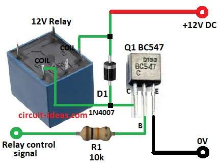
In this circuit 12V relay connects between +12V and Q1 collector and emitter goes to ground, then transistor controls relay like a switch.
Signal to the base makes transistor ON, current flows from +12V through relay coil, collector, emitter and then to ground.
Relay coil makes magnetic field, moves armature, opens or closes relay contacts and controls another circuit
R1 resistor from base to control signal helps limit current, avoid bad switching and need correct value so relay works right.
How it works:
A small control signal makes the transistor act like a gatekeeper.
The transistor turns the relay ON, and the relay handles large currents or voltages that the transistor alone cannot handle.
Moreover, engineers use this arrangement in automation and control systems to provide safe and reliable operation.
Note: Collector-side relay only needs 0.7V base signal to operate.
Advantages:
- Handles high voltage/current well.
- Low voltage drop in saturation and give more current to relay.
- Efficient switching with ON/OFF.
- Works with many control voltages from 3.3V, 5V, 12V.
- The beta effect increases current gain, so the transistor needs less base current.
Disadvantages:
- Need strong base drive circuit.
- Must use flyback diode D1 across relay coil to stop voltage spikes when switching OFF.
2. Relay Connection at the Emitter Side (Common Collector Configuration):
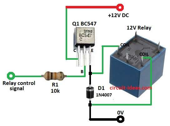
In this circuit relay is between transistor emitter and ground and collector goes to positive supply and transistor works like switch to control relay.
When the base receives current, the transistor turns ON and current flows from the collector to the emitter through the relay coil.
Relay coil makes magnetic field moves switch inside relay and opens or closes another circuit and then relay lets small signal control big power load; it also gives isolation between control side and load side by making system safer.
Note: In emitter-side relay base signal must be slightly higher than relay coil voltage for relay to work.
Advantages:
- Emitter follows base voltage and it can connect directly to logic circuits.
- Easy to fit in systems where relay connects to ground.
Disadvantages:
- Emitter 0.7V lower than base and give less voltage for coil which may affect relay work.
- Transistor may not fully turn ON because of more power loss and less efficiency.
- Relay voltage depends on base voltage which limits high voltage relay use.
Which Configuration is Better?
Most times it is better to put relay on collector side in common emitter design, as this makes switching faster and gives better voltage control and lets transistor work well with better performance.
Collector side (common emitter):
Relay gets full voltage when transistor is ON and works properly.
Transistor can fully saturate by high current, low loss and less heat, as it is good for fast and reliable switching and its easier to ensure relay always gets enough voltage.
Common collector (emitter follower):
Input at base output at emitter has high input impedance and with low output impedance and it is not good for relays because:
- Voltage drop 0.7V which is less voltage to relay.
- Slower switching through which relay responses worse.
- Lower current gain needs more base current.
- Overall, designers prefer the collector side (common emitter) for relay circuits.
- Common collector is less suitable due to voltage drop, slow switching and lower gain.
Formula:
Base resistor (Rb) formula for current limiter BJT:
Rb = (Vs – 0.7) × HFe / Collector current
where:
- Vin is the base voltage from 0.7V to 1.2V
- Vs is the supply voltage
- HFe is the transistor DC gain from datasheet
- Collector current is max current we want to allow
Conclusion:
In this article for Relay Connections at the Collector and Emitter Sides of a Transistor for relay driver it is better to put relay on collector side (common emitter).
It gives better voltage/current control, more efficient switching and relay works well; also emitter side is good only for some low-power cases where simple base drive is more important than efficiency.
Finally, knowing both designs helps designers make better and more reliable circuits.
Leave a Reply