This article explains how to construct a circuit that heats iron items using magnetism.
We call this induction heating.
WARNING: Creating circuits with high currents and voltages can prove harmful.
Do this only under adult supervision and using the right safety equipment.
For beginners this project is not advised.
What is a Induction Heater Circuit:
An electrical device known as an induction heater circuit generates heat in the specified region by using the electromagnetic induction principle.
Eddy currents are frequently generated in conductive materials like metal objects by applying a high frequency magnetic field.
This causes the substance to heat up quickly.
Induction warmers are used in metal hardening, research experiments and cooking equipment.
Circuit Working:

Parts List:
| Category | Description | Quantity |
|---|---|---|
| Resistors | All 1/4 W CFR | |
| 220Ω | 2 | |
| Capacitors | ||
| PPC 330nF | 2 | |
| Semiconductors | ||
| MOSFET IRF540 | 2 | |
| Schottky Diode UF4007 | 2 | |
| Coils As specified in diagram above | 3 |
Induction Heater Working Principle:
To create eddy currents in iron or ferromagnetic metals an induction heater uses a high frequency magnetic field.
Eddy currents along with heating are caused by this mechanism which limits the flow of electrons within the metal.
When considering iron in this situation the heat produced is exactly equal to the square of the current I2 times the metals resistance R.
Because iron has a resistance of 97 nΩ*m high frequency switching applications require perfect designs that use ferrite materials rather than standard iron stamping transformers.
Formula:
Below formula explains how resistance current and heat generation interact in an object like an iron.
It is an example of Joules Law an essential electrical concept.
Heat = I2 × R (Iron)
where,
- Heat which is generally measured in joules J or calories (cal) is the amount of thermal energy that iron generates.
- I2 is the iron current flow squared up and it is measured in amperes
R is the electrical resistance of the irons heating element measured in ohms Ω.
The formulas operation:
When the iron is plugged in and switched ON electricity is conducted by the heating element.
This element offers an important level of resistance to the electrical circuit due to the high resistance material used in its making.
Heat or thermal energy is the result of this fight between electrical and thermal energy.
Zero Voltage Switching Technology:
The circuits for the mentioned induction heaters use ZVS technology to activate the MOSFETs.
ZVS delivers low device heating increasing the operations overall effectiveness.
The circuit is naturally self resonant matching the resonant frequency of the capacitor and coil that are connected to it much like a tank circuit.
Using Oscillator:
A Royer oscillator famous for its simplicity and self resonant working principle is included into the circuit.
MOSFETs are turned ON in sequence with one starting conduction before the other because of inbuilt differences in electronic device parameters.
ZVS Technology and Its Advantages:
With little to no current flowing to their drains ZVS or zero voltage switching assures safe MOSFET activation.
Because of this feature the circuit is capable of handling heavy loads of up to 1 kVA without the need for big heatsinks.
The following formula provides the inductance L1 and capacitance C1 values which directly affect the circuits resonant frequency:
Formula:
Following are the formulas for Simple Induction Heater Circuit:
f = 1 / 2π × √L × C
where,
- In hertz Hz f is the circuits resonant frequency.
- The mathematical constant pi (about equal to 3.14159) is multiplied by two to get 2π.
- For the LC circuit L is the inductors measured inductance in henries H.
- In the LC circuit C is the capacitance of the capacitor measured in farads F.
- This symbol represents the square root √.
How the formula works:
The capacitance C is equal to the weight of the person sitting on a swing set and the inductance L is comparable to the swings length.
With these changes one can modify the swings fundamental oscillation frequency.
The formula basically states that the resonant frequency of the LC circuit is calculated in an adverse form by the square root of the product of capacitance C and inductance L.
Component Specifications:
For the induction heater circuits MOSFETs with recommended ratings of 110V and 33A like the IRF540 can be used.
Heat generation is kept within control by the design even though heatsinks are used.
It is also possible to use N channel MOSFETs with enough ratings without any particular restrictions.
Inductor and Tank Circuit:
By acting as a choke the inductor connected to the main heater coil keeps high frequency content out of the power supply and restricts current to safe levels.
It should be built with large gauge wires to safely carry high currents and its value should be much higher than the work coil usually about 2mH.
For high resonant frequency latching the tank circuit which consists of C1 and L1 needs to be rated to deal with large current and heat magnitudes.
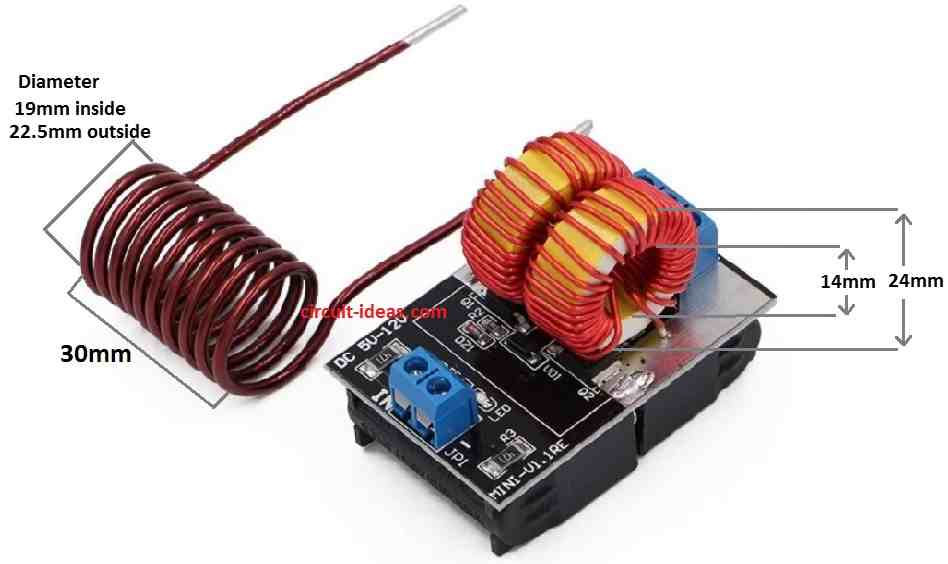
Powerful Induction Heater Design:
An effective ZVS induction idea based on the Mazzilli driver theory is the first design shown here.
This design which has two current limiter coils and one work coil does not require a central tap and ensures quick and efficient heating of heavy loads using a complete bridge push pull action.
Power Output:
With an input voltage of 48V and a current of up to 25A this design can produce up to 1200 watts of electricity.
When the system is working it can melt a bolt that is 1 cm thick in under one minute showing such a level of power.
Because the module for this design is readily available online which is affordable.
How to Build:
To build a Simple Induction Heater Circuit following are the steps one should follow:
Keep the inductor ready:
- Use wires with a high gauge to wind a center tapped coil.
- A value of about 2mH needed.
Put together the tank circuit:
- Connect the metalized PP capacitor e.g. 330nF 400V and the inductor L1 in parallel.
Construct the oscillator:
- Use resistors and capacitors to set up the Royer oscillator making sure the values are correct for stable operation.
Join MOSFETs:
- Connect the chosen N channel MOSFETs such as the IRF540 MOSFETs to the circuit.
- Be sure the connections and placing are correct.
Put Schottky Diodes in Place:
- For fast switching connect Schottky diodes across each MOSFETs gate sources to discharge the gate capacitance when it is not conducting.
Include Quick Recovery Diodes:
- As required by the circuit connect high speed switching or quick recovery diodes.
Check for Connections:
Connection to the Power Supply:
- As one connects the power supply to the circuit should check the voltage and current requirements are met.
- Turn the circuit ON and watch how it behaves.
- Verify that there are no oscillations at the resonance frequency and make sure the parts are not overheated.
Modifications:
- If required fine tune the circuit by modifying certain parts for best results.
Connection for Loading:
- Observe the heating effect after connecting the load such as a work coil to the circuit.
- When conducting load tests be careful and follow to safety rules.
Conclusion:
Connecting skills and electronics understanding are necessary for building electronic circuits.
If one is not familiar with these than think about checking thorough circuit diagrams and instructions or asking an experienced person for help.
When making modifications always turn OFF the circuit and ensure that all safety rules are followed.
Leave a Reply