Simple Missing Pulse Detector Circuit is an electric circuit; it finds when pulse is missing in pulse signal.
Most time it uses 555 timer IC and work like monostable multivibrator; when it gets trigger it gives one output pulse and if next pulse does not come in time then timer is in no reset.
Hence, output pulse finishes then output goes low and then this low output show missing pulse, therefore, watch output to see if any signal breaks or any gap happens.
Circuit Working:
Parts List:
| Components | Values | Quantity |
|---|---|---|
| Resistors | 10k 1/4 watt | 2 |
| Capacitors | 0.1μF | 1 |
| 0.01μF | 1 | |
| Semiconductors | IC 555 | 1 |
| Transistor BC547 | 1 | |
| Push Button | 1 |
Missing Pulse Detector is like a Watchdog:
This circuit is always watching and checking if any signal pulse is missing.
Use IC 555 Chip:
It use special chip called IC 555.
Incoming Pulses:
It think like a heartbeats, many small electric pulses come one after another and this circuit looks at this pulse stream.
IC 555 the main part:
The IC 555 produces a single pulse when it receives a trigger and we can also adjust it to generate a short pulse each time it receives a signal.
How It Work:
Set the Timing:
Inside IC 555 the resistor R2 and capacitor C1 work together like timer and their values decide how long output pulse stays high.
When All is Good:
Each regular pulse from input make IC 555 give its own pulse and we set 555 output pulse a little longer than time between two input pulses.
As a result, if input pulses come regular then next one comes before output pulse ends, so output always stay high and the circuit is happy.
If Pulse is Missing:
If one input pulse does not arrive, the 555 does not trigger, its output pulse ends and the output goes low and this drop indicates a missing pulse
Formula:
555 IC Timing Control in Monostable Mode:
In missing pulse circuit 555 IC uses monostable mode and time of output pulse we can use this formula:
t = 1.1 × R2 × C1
where:
- t is output pulse time in seconds
- R2 is resistor value in ohms
- C1 is capacitor value in farads
This formula help to set how long 555 output stay high and ensure this time is little longer than time between two input pulses.
How to Build:
To build a Simple Missing Pulse Detector Circuit we need to follow the below mentioned steps:
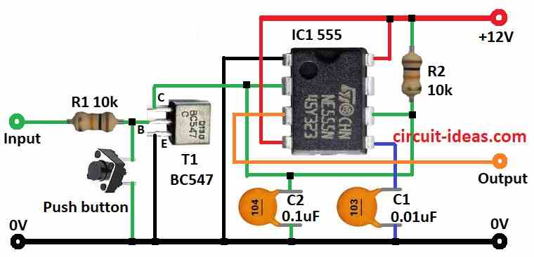
- First, put all parts as shown in above circuit diagram.
- Next, pin 1 of IC 555 goes to ground.
- After that, pin 2 connect to pin 6.
- Then we connect pin 3 to the output pin.
- Now pin 4 and pin 8 goes to positive supply.
- Also, pin 5 connect to ground using capacitor C1.
- Lastly, resistor R2 and capacitor C2 goes from positive supply to ground.
Transistor T1:
- Now collector goes to pin 2 of IC, base connect to input signal using resistor R1 and emitter goes to ground.
- Also, push button connects between transistor base and resistor R1 for testing.
Extra Information:
- Here, capacitor C1 and transistor T1 help with timing and working of IC 555 and push button used for testing it acts like missing pulse.
Conclusion:
Overall, this Simple Missing Pulse Detector Circuit checks if any signal is missing in input; also main part is IC 555 which makes one pulse with fixed time.
Furthermore, capacitor and resistor set this pulse time and by using pulse formula and adjusting parts we can make this circuit work best for our need.
Leave a Reply