We can charge supercapacitor safe and proper with simple and easy to make Supercapacitor Charger Circuit.
Battery does not charges or drain fast, but supercapacitor can do fast charge and drain, because supercapacitor hold less energy than battery.
Also, circuit uses voltage regulator chip like LM317 to control voltage to supercapacitor and regulator checks supercapacitor voltage and compare with reference and then changes output voltage.
Circuit Working:
Parts List:
| Components | Values | Quantity |
|---|---|---|
| Resistors | 1k 1/4 watt | 3 |
| 10k 1/4 watt | 3 | |
| 2.2k 1/4 watt | 1 | |
| 1.5k 1/4 watt | 1 | |
| 3.3k 1/4 watt | 1 | |
| Capacitors | Ceramic 1nF | 1 |
| Supercapacitor 5.5V 1F | 1 | |
| Semiconductors | IC LM317 | 1 |
| IC LM311 | 1 | |
| MOSFET IRFZ44 | 1 | |
| Transistor BC557 | 1 | |
| LED Red 5mm 20mA | 1 | |
| LED Green 5mm 20mA | 1 |
To begin with, this circuit uses 12V DC from wall adaptor and IC LM317 regulator change 12V to 5.5V to charge supercapacitor safe and correct.
Furthermore, the MOSFET works like a switch and supplies 5.5V to the capacitor, also a voltage divider made with resistors R2 and R3 controls the MOSFET.
Hence, for current to flow LM311 pin 3 voltage must be less than 4.86V and voltage divider makes 4.86V from 12V source.
Then LM311 check this voltage while capacitor charging and when capacitor goes above 4.86V then IC LM311 pin 7 goes low and turn OFF the MOSFET and stop charging to prevent overcharge.
We can control the voltage without an op-amp.
Finally, a BC557 PNP transistor drives the LED and when charging finishes and the voltage rises above 4.8V, the MOSFET turns OFF and the LED turns ON to indicate the capacitor is full.
Formula:
LM317 Output Voltage Formula:
Vout = 1.25 * (1 + R2 / R1)
here:
- Vout is output voltage and we want 5.5V.
- R1 is first resistor for example 1k.
- R2 is second resistor for example 3.3k.
By changing R1 and R2 we can change output voltage and in this circuit 1k and 3.3k resistors give near 5.5V which is good for charging the supercapacitor.
Note:
This formula works only for LM317 not for other regulators.
How to Build:
To build a Simple Supercapacitor Charger Circuit we need to follow the below mentioned connections steps:
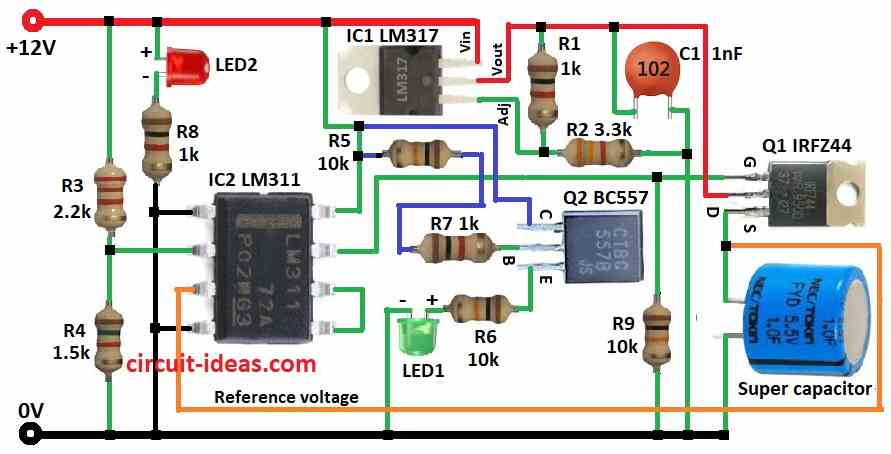
Connection of IC1:
- First, put all parts same like in circuit diagram.
- Next, connect IC1 pin 1 to capacitor C1 using resistors R1 and R2.
- After that, connect IC1 pin 2 to MOSFET Q1 drain.
- Then connect IC1 pin 3 to +12V power.
Connection of IC2:
- First, connect IC2 pin 1 and pin 4 to ground.
- Then connect IC2 pin 2 between resistors R3 and R4.
- After that, connect IC2 pin 3 to reference voltage.
- Now connect IC2 pin 5 and pin 6 together.
- Next, connect IC2 pin 7 to gate of MOSFET Q1 and connect IC2 pin 8 to +12V power.
- Also, connect gate of MOSFET Q1 to IC2 pin 7, connect drain of Q1 to Vout of IC1 and then connect source of Q1 to ground through supercapacitor.
- Now connect Q2 transistor collector to IC2 pin 8, connect Q2 base to IC2 pin 8 through resistors R5 and R7 and then connect emitter of Q2 to ground through resistor R6 and green LED1.
- Also, connect LED2 and resistor R8 from +12V to ground.
- Then connect resistor R9 from gate of Q1 to ground and also connect capacitor C1 from IC1 Vout to ground.
Conclusion:
This Supercapacitor Charger Circuit charges supercapacitor safe and correct; here, LM317 give stable voltage inside safe range of capacitor.
Also, the MOSFET acts like a smart gate and allows current to flow only when the circuit needs charging, then IC LM311 monitors the capacitor voltage and stops charging when the voltage becomes high to prevent overcharging.
Finally, when charging finishes, the BC557 transistor turns ON the LED to indicate the capacitor is full.
Leave a Reply