Transistors are small switches; but how to check if they work or what type they are? then this Simple Transistor Tester Circuit is like a transistor checker.
It is an easy DIY project which uses few parts and it also tells us if transistor is good or bad and also shows if its NPN or PNP like two types.
Furthermore, this circuit does not require any fancy tools.
Circuit Working:
Parts List for both the diagram:
| Components | Values | Quantity |
|---|---|---|
| Resistors (All resistors are assumed to be 1/4 watt) | 1k | 2 |
| Semiconductors | NPN Transistor | 1 |
| PNP Transistor | 1 | |
| 5mm 20mA LED any color | 2 | |
| Battery 9V | 2 |
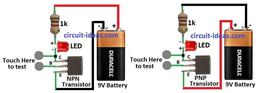
How basic transistor tester works with NPN or PNP transistors:
Use 9V battery, 1k resistor and LED and then connect transistor legs in different ways like in circuit diagram above.
When LED lights up it means connection is good, as brighter LED are the better transistor.
Find transistor type:
Diagrams help us to see if transistor is NPN or PNP and it also shows which leg is base, collector and emitter.
Then bend legs if needed to match the diagram and also this tester works good with normal PNP and Darlington transistors.
How to Build a NPN Transistor Tester:
Build NPN transistor circuit:
- First, connect collector to battery positive through LED and 1k resistor and then connect emitter to battery negative.
How to test NPN transistor:
- After that, turn ON the circuit and touch base and collector with the finger.
- If LED turns ON then the transistor is good and if LED stays OFF then the transistor is bad.
Formulas:
Transistor Tester Circuit with Simple Design & Analysis and to build and understand the circuit we need some basic formulas and ideas.
1. Ohms Law:
V = I × R
- V is the Voltage across a component
- I is the Current
- R is the Resistance
2. Current Limiting Resistor for LED:
To protect LED from too much current we used this formula:
R = (VS − VLED) / ILED
- VS is the Supply voltage like 9V battery
- VLED is the LED forward voltage with 1.8V to 3.3V
- ILED is the LED current e.g. 20mA or 0.02A
3. Power Dissipation:
Be sure parts do not overheat:
P = V × I
- P is the Power
- V is the Voltage
- I is the Current
For Resistor:
PR = I² × R
For Transistor collector-emitter:
PCE = VCE × IC
- IC is the Collector current
- VCE is the Collector-Emitter voltage
Use these formulas to build and test the transistor circuit safely and correctly.
How to Build PNP Transistor Tester
Build PNP Transistor Circuit:
- First, connect collector to battery negative through LED and 1k resistor and also connect emitter to battery positive.
How to Test PNP Transistor:
- Now turn ON the circuit and touch base and collector with the finger.
- If LED turns ON then the transistor is goo and if LED stays OFF then the transistor is bad
Conclusion:
Overall, this easy and Simple Transistor Tester Circuit check if a transistor is working or not if its NPN or PNP; just a few parts needed and watch how LED lights up to understand the transistors type and condition.
Leave a Reply