Simple LED Fading Circuit using IC 555 is small project for LED light which are very cool and save power, as this LED light goes bright and then goes dim slowly.
In this project, we have used 555 IC chip and few other circuit parts which are very easy to make.
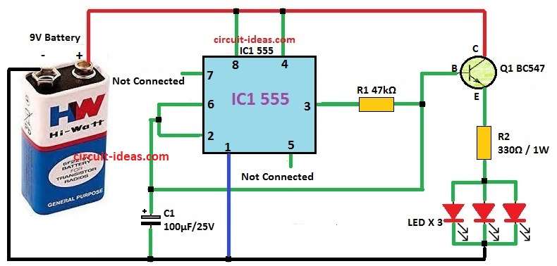
Circuit Diagram:
Parts List:
| Components | Values | Quantity |
|---|---|---|
| Resistors | ||
| 47k 1/4W CFR | 1 | |
| 330Ω 1W CFR | 1 | |
| Capacitors | ||
| Electrolytic 100μF 25V | 1 | |
| Semiconductors | ||
| IC 555 | 1 | |
| Transistor BC547 | 1 | |
| Battery 9V | 1 | |
| LEDs | 3 |
How to Build:
To build a Simple LED Fading Circuit using IC 555 follow the below steps for connections and assembling:
- First, give power to pin 8 and pin 4 and pin 4 will connect to VCC so no reset happen.
- Next, connect pin 1 of IC to ground.
- After that, take pin 5 and connect with 0.1µF capacitor to ground and this help make voltage correct.
- Then take pin 2 and pin 6 join together and It help get stable timing with C1 capacitor.
- Then leave pin 7 open because it is not used as this prevents the LED from turning ON and OFF rapidly
- Next, take pin 3 and connects to transistor base and it also connect to charging capacitor through R1.
- Lastly, LEDs connect to emitter of Q1 transistor with R2 resistor.
Circuit Functions:
Firstly, 555 IC work by charge and discharge of 100µF capacitor C1 and 47k resistor R1.
After that, when capacitor charge and discharge slow it make voltage at transistor base go up and down slow like an soft ON/OFF switch.
And because of this, LED light slowly gets bright and then gets dim and this make nice fading look.
Formulas and Calculations:
Formulas and Calculations for LED Fading Circuit with 555 IC:
Timing Parts:
The LED fading time depend on 100µF capacitor C1 and 47k resistor R1.
To find time constant (τ) it uses:
τ = R × C
For R1 = 47,000 ohms and C1 = 100µF
τ = 47,000 × 100 × 10⁻⁶ = 4.7 seconds
This show how fast LED fade is in and out.
f = 1 / (2 × τ)
So,
f = 1 / (2 × 4.7) = 0.106 Hz
Transistor Base Resistor R2:
To turn transistor ON we need base resistor R2.
Use ohms law:
IB = (VCC − VBE) / R2
where:
- IB is the base current
- VCC is the power supply
- VBE is the voltage drop to about 0.7V for BC547
- R2 is the resistor to transistor base
This calculation help pick right values for fading speed and transistor working.
We can change resistor or capacitor to make LED fade faster or slower.
Conclusion:
To conclude, this Simple LED Fading Circuit using IC 555 show how to make nice LED fading effect using old 555 IC and BC547 transistor.
Also, hobby people can start learning how parts work together in this circuit as it helps to make fun light projects and bring some magic in electronics.
Leave a Reply