This Simple Fade On Fade Off LED Circuit makes the LED turn ON and OFF gradually instead of suddenly; also the circuit creates a dimming effect with smooth transitions that look pleasant to the eye.
Circuit Working:
Parts List:
| Components | Values | Quantity |
|---|---|---|
| Resistors | 100k 1/4 watt | 3 |
| 1Ω 0.5W (or 8.2Ω depending on LED color) | 1 | |
| Capacitors | Electrolytic 100μF 25V | 1 |
| Semiconductors | Transistor BJT BD679 | 1 |
| ON/OFF Switch | 1 | |
| LEDs 3W 3.3V | 3 |
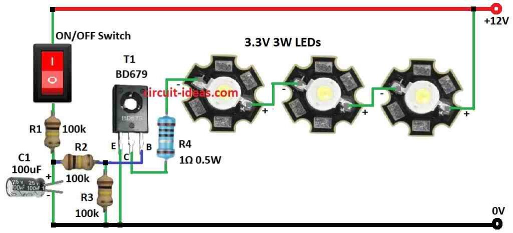
This Fade On Fade Off LED circuit uses a BJT transistor to control the current for three LEDs, also the design supports three 3.3V, 3W LEDs and operates from a 12V power source.
But be sure LED voltage match our power supply.
How circuit works:
Switch OFF means no current to transistor base then transistor will be OFF and the LEDs will also be OFF and switch ON means current goes through R2 resistor to transistor base then transistor turns ON and power flows to LEDs through resistor R1 and LEDs will turn ON.
Furthermore, capacitor C1 smooth the current and it charges and give more current to transistor base and then the LEDs fade ON slowly.
When fully charged then the capacitor keep current is steady and LEDs stay ON and switch OFF means Capacitor C1 discharge through resistor R4 and current to base drop slowly and LEDs fade OFF slowly.
Speed of fade ON/OFF depends on resistor and capacitor values, so try different values for best result.
Formulas and Calculations:
Above is LED circuit that fades ON and OFF and resistor R3 and capacitor C1 together make the fade effect.
Fade time depends on RC time constant:
tau = R × C
where:
- tau is the time in seconds
- R is the resistance in ohms
- C is the capacitance in farads
Example:
R3 = 100kΩ and C1 = 100µF
tau = 100,000 × 100×10⁻⁶ = 10 seconds
So LED takes about 10 seconds to fade ON or OFF.
Change fade time by changing R3 or C1 like:
- Bigger R3 or C1 then slower the fade
- Smaller R3 or C1 then faster the fade
Ensure capacitor has time to charge/discharge fully.
Try different values to get fade time we like.
How to Build:
To build a Simple Fade On Fade Off LED Circuit follow the connections process mentioned below:
- First, gather all the circuit parts as shown in circuit diagram
- Next, connect emitter of transistor T1 to ground.
- After that, connect collector of T1 to 12V positive through 3 LEDs in series and R4.
- Then connect base of T1 to middle point of R2 and R3.
- Now connect capacitor C1, resistor R1 and ON/OFF switch in series from ground to 12V.
- Also, connect R3 to ground between T1 base and R2 and connect 3 LEDs in series with R4 resistor from 12V to transistor collector.
Safety Tips:
- Use proper rated soldering iron and power supply and be careful with high power LEDs and heat.
- If not sure about electronics then ask an expert for help.
Conclusion:
To conclude, this Simple Fade On Fade Off LED Circuit makes LED light look smooth and nice, also using transistor and capacitor we can make cool fade effect like natural light.
Moreover, it is good for DIY lighting or creative electronics projects.
Leave a Reply