• Skip to primary navigation
  • Skip to main content
  • Skip to primary sidebar

Circuit Ideas for You

Get free circuit ideas online.

  • Home
  • Privacy Policy
  • About
Home » Sound Activated LED Circuit with Arduino

Sound Activated LED Circuit with Arduino

Last updated on 22 September 2025 by Admin-Lavi Leave a Comment

Make our Lights Dance with Sound!

This Sound Activated LED Circuit with Arduino turns every clap, snap or beat into a colorful light show.

It is a fun and easy project that brings sound and LEDs to life.

Perfect for beginners who want to see their music or sounds in action!

Circuit Coding:

int soundSensor = A0;
int ledPins[] = {2,3,4,5,6};
int sensorValue = 0;

void setup() {
for(int i=0; i<5; i++) {
pinMode(ledPins[i], OUTPUT);
}
pinMode(soundSensor, INPUT);
Serial.begin(9600);
}

void loop() {
sensorValue = analogRead(soundSensor);
Serial.println(sensorValue);
if(sensorValue > 400) {
for(int i=0; i<5; i++) {
digitalWrite(ledPins[i], HIGH);
}
} else {
for(int i=0; i<5; i++) {
digitalWrite(ledPins[i], LOW);
}
}
}

Coding Explanation:

  • Variable soundSensor store A0 pin.
  • Array ledPins store LED pins.
  • Setup function set LED pins output, sensor pin input.
  • Loop read analog value from sensor.
  • If value is more than 400 then all LEDs ON.
  • Else all LEDs are OFF.
  • Serial print show sensor values for testing.

Circuit Working:

Sound Activated LED Circuit Diagram with Arduino

Parts List:

ComponentQuantity
Resistors
220Ω 1/4 watt5
Semiconductors
Arduino UNO1
Sound Sensor Module1
LEDs any 5mm 20mA5

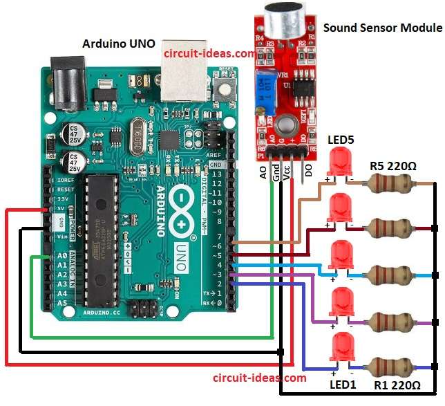
Sound sensor get power from Arduino 5V and GND.

Sensor detect sound and send signal to Arduino A0.

Arduino read signal and turn ON/OFF LEDs on pins D2 to D6.

Each LED need resistor from R1 To R5 to protect from too much current.

When sound is loud then more LEDs light up.

Circuit is simple with no button and no switch.

How to Build:

To build a Sound Activated LED Circuit with Arduino follow the below mentioned steps for connections:

  • Take all parts same as circuit diagram.
  • Sound sensor VCC go to Arduino 5V.
  • Sound sensor GND go to Arduino GND.
  • Sound sensor OUT go to Arduino A0.
  • LEDs connect to Arduino pins D2, D3, D4, D5, D6 with resistors R1 to R5.
  • Each LED anode go to Arduino pin.
  • Each LED cathode go to GND through resistor.

Conclusion:

Sound Activated LED Circuit with Arduino is simple project.

It shows sound control LEDs.

Same idea can be used for fan, light, motors.

Circuit is easy to make and is good for beginners.

References:

How to connect an ultrasonic sensor and a sound sensor on one breadboard

Filed Under: Arduino Projects, Sensors and Detectors

About Admin-Lavi

Lavi is a B.Tech electronics engineer with a passion for designing new electronic circuits. Do you have questions regarding the circuit diagrams presented on this blog? Feel free to comment and solve your queries with quick replies

Previous Post: « Whistle Controlled Light Circuit using Arduino
Next Post: Small UPS Circuit for Router Backup »

Reader Interactions

Leave a Reply Cancel reply

Your email address will not be published. Required fields are marked *

Primary Sidebar


Categories

  • 555 Timer Projects (18)
  • Alarm Circuits (57)
  • Amplifier Circuits (78)
  • Arduino Projects (102)
  • Audio Circuits (143)
  • Automation Circuits (4)
  • Automobile Circuits (22)
  • Battery Charger Circuits (75)
  • DIY Projects (41)
  • Free Energy (13)
  • Heater and Temperature Controllers (21)
  • High Voltage (11)
  • Hobby Circuits (6)
  • Indicator Circuits (57)
  • Inverter Circuits (19)
  • IoT projects (1)
  • LDR Circuits (34)
  • LED and Lamps (173)
  • Meters and Testers (35)
  • Mini Projects (23)
  • Motor Controllers (22)
  • Oscillator Circuits (44)
  • Power Supply Circuits (180)
  • Remote Control Circuits (9)
  • Security and Protection (42)
  • Sensors and Detectors (156)
  • Solar Circuits (32)
  • Timer Circuits (48)
  • Transistor Circuits (135)
  • Transmitter Circuit (18)
  • Tutorials (8)
  • Voltage Regulator (1)
  • Water Level Controller (7)

Recent Posts

  • Low Noise Transistor Preamplifier Circuit
  • Transistor Based Medium Impedance Preamplifier Circuit
  • Low Cost DIY Microphone Circuit using Normal Speaker
  • Low Impedance Input Transistor Preamplifier Circuit
  • 12V Dynamic Mic Preamplifier Circuit

Recent Comments

  1. Transistor Based Medium Impedance Preamplifier Circuit - Circuit Ideas for You on Low Impedance Input Transistor Preamplifier Circuit
  2. Admin-Lavi on Alternate Red Green LED Flasher Circuit
  3. Admin-Lavi on Alternate Red Green LED Flasher Circuit
  4. Mike on Alternate Red Green LED Flasher Circuit
  5. angel on 12 Watts Amplifier Circuit using Transistors

Copyright © 2026 | New Circuit Ideas