• Skip to primary navigation
  • Skip to main content
  • Skip to primary sidebar

Circuit Ideas for You

Get free circuit ideas online.

  • Home
  • Privacy Policy
  • About
Home » Simple LED Circuit

Simple LED Circuit

Last updated on 29 June 2026 by Admin-Lavi Leave a Comment

Want to light an LED using a battery? then this Simple LED Circuit using 9V Battery shows how; as it is the first step to learn electronics and current flow.

In addition, just with one battery, one resistor and one LED, we can make it in few minutes and see our LED glow bright.

Circuit Working:
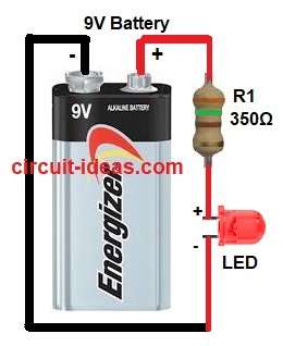
Simple LED Circuit Diagram

Parts List:

ComponentsValuesQuantity
Resistor350Ω1
Semiconductors2V Red LED1
9V DC Battery1

The 9V battery gives power to LED through a resistor and moreover, LED lights only when current flows in correct direction.

Then resistor controls the current going to LED and without resistor a LED will burn because current is too high.

Formula with Calculation:

The formula for Simple LED Circuit.

Battery voltage = 9V

LED voltage drop = 2V (red LED)

Required current for LED = 20mA = 0.02A

Voltage drop across resistor = 9 – 2 = 7V

Resistor value R = V / I = 7 / 0.02 = 350 ohms

So we used R1 = 350Ω resistor.

How to Build:

To build a Simple LED Circuit follow the below steps:

  • First, gather all the parts as in circuit diagram.
  • Next, connect positive (+) terminal of 9V battery to one end of resistor R1 and connect other end of resistor to LED anode.
  • Then connect LED cathode to negative (-) terminal of battery.

Conclusion:

To conclude, this Simple LED Circuit is very easy to make, as it helps beginners to learn about LED polarity and resistor use; therefore always use resistor to protect LED from high current.

Filed Under: Indicator Circuits, LED and Lamps, Mini Projects

About Admin-Lavi

Lavi is a B.Tech electronics engineer with a passion for designing new electronic circuits. Do you have questions regarding the circuit diagrams presented on this blog? Feel free to comment and solve your queries with quick replies

Previous Post: « IR Burglar Alarm Circuit
Next Post: Sound And Light Metronome Circuit using Transistors »

Reader Interactions

Leave a Reply Cancel reply

Your email address will not be published. Required fields are marked *

Primary Sidebar


Categories

  • 555 Timer Projects (137)
  • Alarm Circuits (81)
  • Amplifier Circuits (94)
  • Arduino Projects (103)
  • Audio Circuits (190)
  • Automation Circuits (150)
  • Automobile Circuits (40)
  • Battery Charger Circuits (89)
  • DIY Projects (437)
  • Free Energy (12)
  • Heater and Temperature Controllers (32)
  • High Voltage (24)
  • Hobby Circuits (244)
  • Indicator Circuits (63)
  • Inverter Circuits (17)
  • IoT projects (12)
  • LDR Circuits (47)
  • LED and Lamps (201)
  • Meters and Testers (44)
  • Mini Projects (392)
  • Motor Controllers (26)
  • Oscillator Circuits (70)
  • Power Supply Circuits (245)
  • Radio Frequency (8)
  • Remote Control Circuits (12)
  • Renewable energy (20)
  • Security and Protection (128)
  • Sensors and Detectors (236)
  • Solar Circuits (31)
  • Timer Circuits (63)
  • Transistor Circuits (178)
  • Transmitter Circuit (19)
  • Tutorials (33)
  • Voltage Regulator (67)
  • Water Level Controller (10)

Recent Posts

  • Low Current Controlled Battery Charger Circuit using LM723 IC
  • 741 Op-Amp Treble Booster Circuit
  • Simple Diode and Transistor Based Audio Limiter Circuit
  • Simple 500mW Speaker Driver Circuit
  • Easy DIY LM386 Audio Amplifier Circuit

Recent Comments

  1. Admin-Lavi on High Voltage Fence Charger Circuit
  2. etere on High Voltage Fence Charger Circuit
  3. Admin-Lavi on High Voltage Fence Charger Circuit
  4. egidio grzinic on High Voltage Fence Charger Circuit
  5. Logic OR Gate Circuit using Transistors - Circuit Ideas for You on Automatic Street Light Circuit using LDR

Copyright © 2026 | New Circuit Ideas