Music needs rhythm and a metronome helps us keep that rhythm perfect; also this small project for Sound And Light Metronome Circuit using Transistors turns light into beat.
When light changes then sound speed also change and hence, this project is simple, fun and easy to build.
What is Metronome:
Metronome is small device that gives steady beat and it makes tick-tick sound at a set speed, furthermore, musicians use it to play in right rhythm.
The speed can be slow or fast, which musicians call tempo; older metronomes use a pendulum, while modern metronomes use electronic circuits to keep accurate timing during musical performances.
Circuit Working:
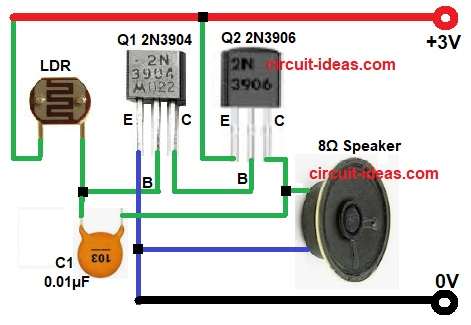
Parts List:
| Components | Quantity |
|---|---|
| Resistor | |
| LDR standard | 1 |
| Capacitor | |
| Ceramic 0.01µF | 1 |
| Semiconductors | |
| Transistors 2N3904, 2N3906 | 1 each |
| Speaker 8Ω | 1 |
| Power Supply 3V | 1 |
LDR1 is light sensor and when light is bright, LDR resistance becomes low and when light is dark its resistance becomes high.
Then transistor Q1 2N3904 and Q2 2N3906 work as amplifier and oscillator pair and capacitor C1 0.01µF gives feedback between collector of Q2 and base of Q1; also, because of this feedback and circuit starts oscillating
Oscillation frequency depends on LDR resistance and C1 value and then speaker converts these oscillations into clicking or tone sound.
Finally, when light level changes then tone speed or pitch also changes like metronome tick.
Formulas with Calculation:
Below is the general formula for Sound And Light Metronome Circuit:
Approximate frequency formula: f = 1 / (2 × R × C)
Here,
- R is resistance of LDR in ohms
- C is capacitor value (in farad)
Just Imagine:
If LDR resistance in light = 10kΩ
C = 0.01µF = 0.01 × 10⁻⁶ F
Then f = 1 / (2 × 10,000 × 0.01 × 10⁻⁶)
f = 5,000 Hz
In darkness if LDR = 100kΩ
f = 1 / (2 × 100,000 × 0.01 × 10⁻⁶)
f = 500 Hz
So tone becomes slower in dark and faster in light.
How to Build:
To build a Sound And Light Metronome Circuit using Transistors follow below steps:
- First, gather all the components as shown in circuit diagram:
- Next, connect emitter pin of transistor Q1 to ground and on end of 8 ohm speaker, connect base pin of transistor Q1 to junction of LDR and capacitor C1 and connect collector pin of transistor Q1 between the the base of Q2 and one end of LDR
- Then connect emitter pin of transistor Q2 to +3V power supply, connect base pin of transistor Q2 to collector of Q1 and then connect collector pin of transistor Q2 to other end of speaker
Conclusion:
To conclude, this Sound And Light Metronome Circuit using Transistors is simple and fun project, it shows how light can control sound; also we can use it as light alarm, teaching demo or simple sound effect.
In addition, it works best with small changes in light and gives clear tone from the speaker.

Leave a Reply