Have fun making this Simple Lie Detector Circuit using Transistors.
Real lie detectors are very hard and complicated so this one is not perfect; but it is fun way to see how body react when its in stress.
Also, this circuit works by detecting changes in sweat to check whether someone may be telling the truth or lying, people usually sweat more when they feel scared or nervous.
Be careful: Do not use this for real lie test use it is just for fun only.
What is a Lie Detector Circuit:
People call a lie detector circuit a polygraph or truth checker device and it checks body signals that may change when a person lies.
Idea is simple when person lie or feel stress body changes little without knowing; also lie detector watch these feelings and try to know if person says truth or lie.
Hence, the following section explains how to make the circuit and how it works:
Circuit Working:
Parts List:
| Components | Values | Quantity |
|---|---|---|
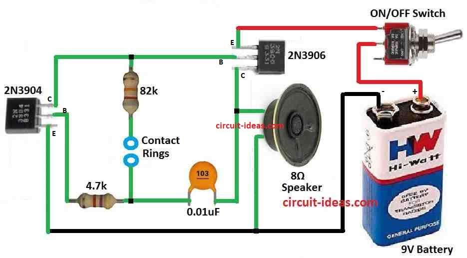
| Resistors | 4.7k CFR, 82k CFR 1/4 watts | 1 each |
| Capacitor | Ceramic 0.01µF | 1 |
| Semiconductors | Transistors 2N3904, 2N3906 | 1 each |
| Speaker 8Ω | 1 | |
| ON/OFF Switch | 1 | |
| Battery 9V | 1 | |
| Blue Rings | 2 |
The above circuit, starts working when person put fingers on blue rings and switches ON the power.
If fingers are dry and person is calm then speaker make low sound that mean there is no stress; but when person feel scared or nervous then small amount of salty water come from fingers.
Also, circuit catches this fast and speakers sound become more sharp and loud, hence sound changes show person maybe having stress and maybe telling lie or not telling full truth.
Hence, this smart way lie detector circuit help see feelings and maybe find hidden truth.
Formula:
Below is formula for finding resonant frequency of LC circuit:
f = 1 / 2π√LC
where:
- f is the resonant frequency in hertz Hz.
- L is inductance in henry H.
- C is capacitance in farads F.
- π (pi) is math number about 3.14159.
- √ means square root.
This formula say frequency goes lower when L or C become bigger; so more inductance or capacitance = lower frequency.
Opposite is also true like small L or C = higher frequency.
Note:
This formula only works good when circuit have no resistance; also actual circuits always have some resistance so real frequency may change a little and become weaker.
However, many electronics use this idea like oscillators, filters and radio tuning.
How to Build:
To build a Simple Lie Detector Circuit follow the below mentioned connections steps:
Get the Transistors Ready:
- First, put PNP transistor 2N3906 and NPN transistor 2N3904 in right place.
- Also, make sure the wires and components connect properly so the circuit works smoothly.
Connect the Blue Rings:
- Then put the blue rings at correct place in circuit and these rings are for touching with fingers and they help to find small body changes.
Connect to Power Supply:
- Then, connect a 9V battery to power the circuit and check that all wires connect properly; the circuit also needs a stable power supply for the best results.
Build the Feedback Oscillator:
- Also, this lie detector uses 2 transistor feedback oscillator as main part.
- Use the above formulas to find correct resistor and capacitor values for good frequency, which will help the oscillator work and find small changes in body signals.
Connect the Audio Output:
- After that, add 8 ohm speaker to circuit for sound output and this speaker makes different sounds based on circuits frequency.
- Also, this will help to understand if person maybe lying or not.
Conclusion:
Overall, police departments, employers and others use this Simple Lie Detector Circuit using Transistors, but many people still question its accuracy.
Here, the success of lie test depend on many things like how person feel or how well they hide emotion.
Also, lie detectors must follow legal rules because courts in many countries can use lie test results as evidence.
Leave a Reply