The Simple FM Radio Jammer Circuit generates a signal that blocks normal FM radio transmission; additionally, it transmits noise or a fake signal on the same frequency, thereby disrupting the real FM signal.
Main parts:
- Transistor for making signal oscillator
- Capacitors for tuning
- Coil to make radio frequency signal
- Resistors to keep circuit stable
Furthermore, transistor work like oscillator and make RF signal and coil and capacitor set the frequency of this signal, also change trimmer capacitor to change jammer frequency inside FM band.
Hence, when jammer send signal on same frequency as radio it block that station.
Legal Warning:
FM jammers can block important signals, including emergency service communications, moreover, many countries ban their use due to interference risks and legal restrictions.
So always follow the local laws before making or using such circuit and also this information is only for learning.
Circuit Working:
Parts List:
| Components | Quantity |
|---|---|
| Resistors | |
| 15k 1/4 watt | 1 |
| 3.9k 1/4 watt | 1 |
| 220Ω 1/4 watt | 1 |
| Capacitors | |
| Ceramic 0.01μF | 1 |
| Ceramic 5.6pF | 1 |
| Electrolytic 10μF 25V | 1 |
| Adjustable capacitor trimmer 35pF | 1 |
| Semiconductors | |
| Transistor 2N2222 | 1 |
| Inductor L1 (6 turns of 16AWG enameled copper wire on a 9mm plastic former) | 1 |
| Battery 9V | 1 |
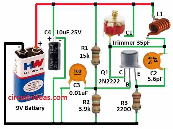
To begin with, in this circuit transistor Q1 works as oscillator and Coil L1 and capacitors C1, C2, C3 make resonant circuit; also this sets the frequency of the signal.
Change value of L1 and trimmer capacitor C1 to change the frequency, coil L1 also send out the signal to send it into air.
Finally, if circuit work well it make signal in FM band and can block FM radio nearby, so for best performance build circuit on good PCB.
Formulas:
Important Ideas & Formulas for FM Jammer Circuit:
To make and tune FM jammer we need to know how to set frequency using coil and capacitor.
LC Resonant Frequency:
Coil L and capacitor C set how fast signal (frequency) goes.
Formula:
f = 1 / (2π × √(L × C))
where:
- f is the frequency in hertz Hz
- L is the inductance in henry H
- C is the capacitance in farad F
Find L or C for a Given Frequency:
To find correct C:
C = 1 / ((2πf)² × L)
To find correct L:
L = 1 / ((2πf)² × C)
Use of Trimmer Capacitor:
Trimmer capacitor help adjust frequency.
Total Capacitance = Fixed Cap + Trimmer Cap
Formula:
Ctotal = Cfixed + Ctrimmer
where,
- Change Ctrimmer to move frequency a little up/down.
How to Build:
To build a Simple FM Radio Jammer Circuit follow the below mentioned steps for connections:
- First, Q1 collector connect to one side of C1 trimmer and other side of C1 goes to +9V, Q1 base connect to C3 capacitor and to ground and then Q1 emitter goes to ground through R3 resistor.
- After that, R1 and R2 goes from +9V to ground which joined between C3 and Q1 base and L1 coil connect between +9V and Q1 collector.
- Next, C2 capacitor goes between collector and emitter of Q1.
- Also, C4 capacitor connect from +9V to ground for power filtering.
- Lastly, use 9V battery, connect positive to +9V line and negative to ground.
Conclusion:
Overall, this Simple FM Radio Jammer Circuit uses Q1 transistor to make radio frequency signal, also change trimmer capacitor to set the jammer frequency if required.
Moreover, if tuned right it block FM radio in small area, FM jammer can block real radio like emergency or police signal.
Also, in many countries its illegal to build or use, so remember this information is only for learning and always follow the local law.
Leave a Reply