In audio amplifiers, achieving good sound quality with low power consumption and long-term reliability is very important.
Therefore, this 50-Watt Audio Amplifier Circuit delivers strong audio output while operating efficiently and reliably over extended periods.
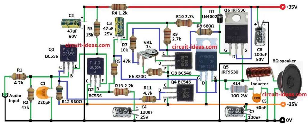
Furthermore, it uses both MOSFET and BJT to make clear sound and can run 8 ohm speaker with full 50 watt power.
Circuit Working:
Parts List:
| Components | Values | Quantity |
|---|---|---|
| Resistors (All resistors are 1/4 watt unless specified) | 15k | 1 |
| 1.2k | 1 | |
| 680Ω | 1 | |
| 560Ω | 1 | |
| 820Ω | 1 | |
| 10k | 1 | |
| 2.2k | 1 | |
| 10Ω 2W | 1 | |
| 47k | 2 | |
| 2.7k | 2 | |
| 4.7k | 2 | |
| Preset 1k | 1 | |
| Capacitors | Ceramic 220pF | 1 |
| Ceramic 68nF | 1 | |
| Electrolytic 47μF 50V C2 | 1 | |
| Electrolytic 47μF 25V | 1 | |
| Electrolytic 100μF 50V C6 | 1 | |
| Electrolytic 100μF 25V | 2 | |
| Semiconductors | MOSFET IRF530 | 1 |
| MOSFET IRF9530 | 1 | |
| Transistor BC556 | 2 | |
| Transistor BC546 | 2 | |
| Diode 1N4002 | 1 | |
| Inductor Coil (12 turns of enameled copper wire on a 1cm diameter plastic former) | 1 | |
| Speaker 8Ω | 1 |
To begin with, this 50 watt audio amplifier gives strong sound with low distortion.
First, Q1 and Q2 transistors work as differential amplifier to start the circuit and R1 controls input current and C1 removes high frequency noise and blocks DC from input.
Next, step is driver stage with Q3 and Q4 transistors and output stage uses IRF530 and IRF9530 MOSFETs in push-pull setup.
Then L1 coil connects output to speaker and R14 and C5 help reduce noise and C6 and C7 clean the power supply; after that, VR1 sets the idle (quiescent) current.
Also, build circuit on good PCB and use +/-35V dual power supply and for L1 wind 12 turns of copper wire enameled on 1 cm plastic tube.
Moreover, all other electrolytic capacitors can be 10V or 15V but C6 and C7 must be 50V.
MOSFETs need heat sink with bigger is better, so a 8x4x4 inch aluminum finned heat sink is good.
How to Build:
To build a 50 Watts Audio Amplifier Circuit follow the below mentioned steps:
- First, Q1 receives the input audio signal, while R1 and C1 connect the base to ground, then Q1 and Q2 share a common emitter, also, the collector of Q1 connects to −35 V through R12 and through R11, drives the base of Q4.
- Next, Q2 collector goes direct to -35V and then Q2 base goes to ground via R13 and C4 and also connect to R5, C3 and R10 to +35V.
- After that, Q3 base goes to middle leg of preset VR1 emitter go to second leg of VR1 through R6, collector to R9.
- Then Q4 base connect to Q1 collector, emitter to -35V and collector to Q3 emitter.
- Now Q5 gate connect to Q3, emitter drain to -35V and source to L1 and Q6 source.
- Also, L1 goes to one side of speaker and other side to ground and R14 and C5 connect from Q5 source to ground noise filter.
- Next, C7 connect from -35V to ground power filter.
- Then Q6 gate connect to +35V through D1 and also R7 and R8 from VR1 third leg and also Q6 drain goes to +35V and source join Q5 source.
- Finally, C2 and C6 clean power filter capacitors.
Conclusion:
To conclude, this 50 Watts Audio Amplifier Circuit uses good parts and strong layout, also sound come out loud and clear.
Moreover , circuit works good for home and pro audio both and also gives steady and clean sound all time.
Leave a Reply