18 Watt MOSFET Audio Amplifier Circuit is good for home sound, small PA or personal audio work, as it give medium power to sound signal; also this amplifier uses MOSFET (Metal-Oxide-Semiconductor Field-Effect Transistor).
Furthermore, it offers several advantages, including cooler operation, lower distortion and higher efficiency.
A MOSFET is a three-terminal device used in many electronic circuits, its insulated gate structure prevents leakage current and allows it to operate similarly to a JFET while providing improved performance.
MOSFET amplifier means amplifier use MOSFET and it is good for linear amplifier because it handle less load; also many circuits can use this type amplifier as it have many uses.
Circuit Working:
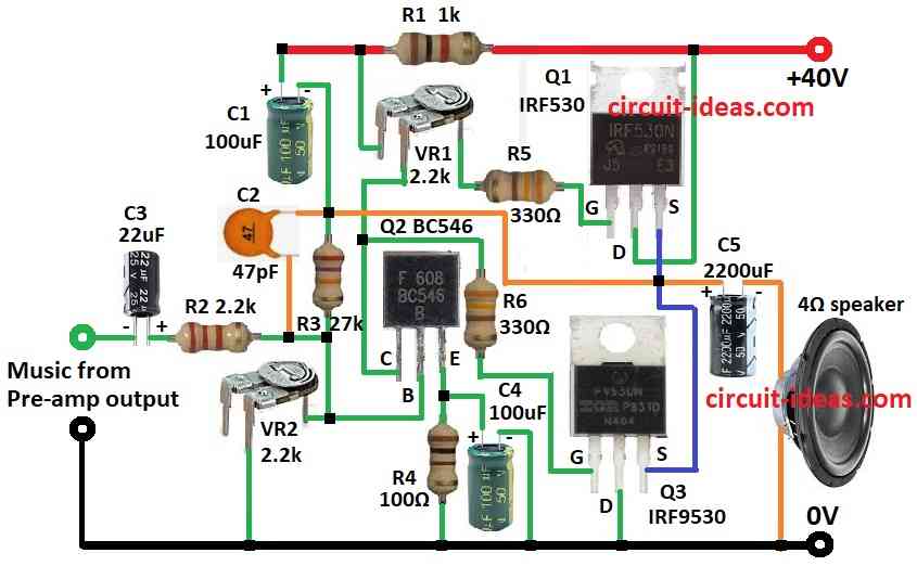
Parts List:
| Components | Values | Quantity |
|---|---|---|
| Resistors (All resistors are 1/4 watt unless specified) | 1k | 1 |
| 2.2k | 1 | |
| 27k | 1 | |
| 100Ω | 1 | |
| 330Ω | 2 | |
| 2.2k | 2 | |
| Capacitors | Ceramic 47pF | 1 |
| Electrolytic 100μF 50V | 2 | |
| Electrolytic 22μF 25V | 1 | |
| Electrolytic 2200μF 50V | 1 | |
| Semiconductors | MOSFET IRF530 | 1 |
| MOSFET IRF9530 | 1 | |
| Transistor BC546 | 1 | |
| Speaker 4Ω | 1 |
To begin with, this is small audio amplifier which makes strong sound using few parts and sound quality is good, as it uses shunt feedback with only one transistor, two MOSFETs, some resistors and capacitors which give 18 watts for 4 ohm speaker.
Moreover, the circuit need +40V power to work, as high voltage help push 4 ohm speaker with enough power, also it is good power supply which keep sound clean and give same power in different loads.
Hence, its best to use DC voltage regulator to give 40V and more than 2 amps.
Here, the IRF530 N-channel MOSFET boosts the audio signal, as its low on-resistance and high input impedance make it well suited for this purpose.
In addition, the IRF9530 P-channel MOSFET works with the IRF530 in a push-pull configuration and together they provide a strong and stable output.”
The BC546 NPN transistor acts as a driver and helps the MOSFETs operate more effectively while providing additional gain.
Therefore, when we choose the components and design carefully, this circuit delivers strong audio output for a wide range of applications.”
Formulas:
Some useful formulas help in making audio amplifier for power, parts value and how well it works.
Power Output Formula:
To find power output into load:
P = Vout² / Rload
where,
- P is the power in watts
- Vout is the RMS output voltage
- Rload is the load resistance like 4 ohm
To find how much the voltage increases:
AV = Vout / Vin
where,
- AV is the voltage gain
- Vout is the output voltage
- Vin is the input voltage
Power Supply Needs:
Power supply must give enough voltage and current.
Current from supply is:
Isupply = Poutput / Vsupply
where,
- Isupply is the supply current
- Poutput is the power output
- Vsupply is the supply voltage
To stop MOSFETs from getting hot and find how much power they waste:
Pdissipated = VDS × ID
where,
- Pdissipated the power wasted
- VDS is the drain to source voltage
- ID is the drain current
Use heatsink if this value is high.
Capacitor Value for C3 and C5:
Used for coupling and for bypassing, hence formula to find capacitor is:
C = 1 / (2πfcR)
where,
- C is the capacitor value
- fc is the cutoff frequency
- R is the resistance it connects to
Feedback Network:
Amplifier gain also set by feedback resistors:
ACL = 1 + Rf / Ri
where,
- ACL is the closed loop gain
- Rf is the feedback resistor R3
- Ri is the input resistor R2
Therefore, these formulas help build and understand audio amplifiers and check how they perform.
How to Build:
To build a 18 Watt MOSFET Amplifier Circuit follow the below mentioned steps:
- First, gather all the parts as shown in circuit diagram
- Next, Q2 collector goes to gate of Q3 through R6 and to one leg of preset VR1, Q2 base connects to first leg of VR2 and second leg of VR2 goes to ground, from base of Q2 connect R3 and C1 to +40V and then Q2 emitter goes to ground through R4 and C4 also connects to ground between emitter and R4.
- Also, between base of Q2 and R3 connect R2 and C3 in series and this goes to music input from preamp.
- Then Q1 gate connects from R5 to middle leg of VR1, Q1 drain goes to +40V, and source of Q1 connects to source of Q3.
- After that, Q3 gate connects to Q2 collector and Q3 drain goes to ground, Q3 source connects to Q1 source.
- Now C2 connects between R2 and R3 and one side of speaker goes through C5 to this point and other side of speaker goes to ground.
- Lastly, R1 connects to +40V supply.
Safety Tips:
- Handle and test carefully and use proper heat sinks for MOSFETs.
- Also, double check power connections before turning ON and use good quality parts and strong DC power supply.
Conclusion:
Overall, this simple 18 Watt MOSFET Audio Amplifier Circuit gives strong sound using few parts, also with good power supply and safety steps it work well for many audio uses.
Finally, it is cheap and good for home projects.
Leave a Reply