To begin with, in this Simple LM386 Audio Amplifier Circuit we use one popular chip called LM386 to make small sound amplifier circuit, hence it does not cost much and is easy to make and can make speaker or music player sound louder.
Also, it is not very powerful for big show but good for small projects and is good way to learn electronics and make music sound better.
What is a LM386 Audio Amplifier:
The LM386 is a very common chip for building low-power audio amplifiers and people use it in small audio devices like portable speakers, intercoms, and DIY projects because it is easy to use, affordable and simple.
Also, it help to make sound louder in small electronics projects.
Understanding LM386:
LM386 is old but still useful audio amplifier chip with class AB type and people still use it in small speakers and portable stereo.
Like in pin diagram LM386 comes in common 8-pin DIP package.
Pin Functions and Gain Control:

First, when we look at the pin diagram the design appears simple and requires only a few wires.
Normal gain is 20 and it works like that with pin 1 and pin 8 and if we put capacitor between pin 1 and 8 gain goes up to 200 because it skip the inside resistor.
Also, op-amp inside chip uses pin 2 and 3 and this pin 2 is for inverting and pin 3 is for non-inverting input.
Furthermore, audio input come from mic, laptop, music player or phone and connect to input pin.
Power Supply and Output:
Pin 6 and pin 4 are for power and this chip can take up to 15V but in this project we have used 12V power.
Pin 7 help with decoupling but we need to put capacitor to connect ground there.
Moreover, output comes from pin 5 and before connecting to speaker we must control it properly to stop any damage from DC signal.
Applications of LM386:
The LM386 chip is widely used in the audio world and serves as the main component in small speakers, music players, laptop speakers, TV audio systems, FM radios, microphone voice recorders and battery-powered speakers.
Hence, it can work in many ways as it is popular in many audio projects.
Circuit Working:
Parts List:
| Components | Values | Quantity |
|---|---|---|
| Resistor | 10Ω 1/4 W CFR | 1 |
| Potentiometer 10k | 1 | |
| Capacitors | Ceramic 0.047µF | 1 |
| Electrolytic 10µF 25V | 3 | |
| Electrolytic 1000µF 25V | 1 | |
| Semiconductor | IC LM386 | 1 |
| Speaker 8Ω | 1 |
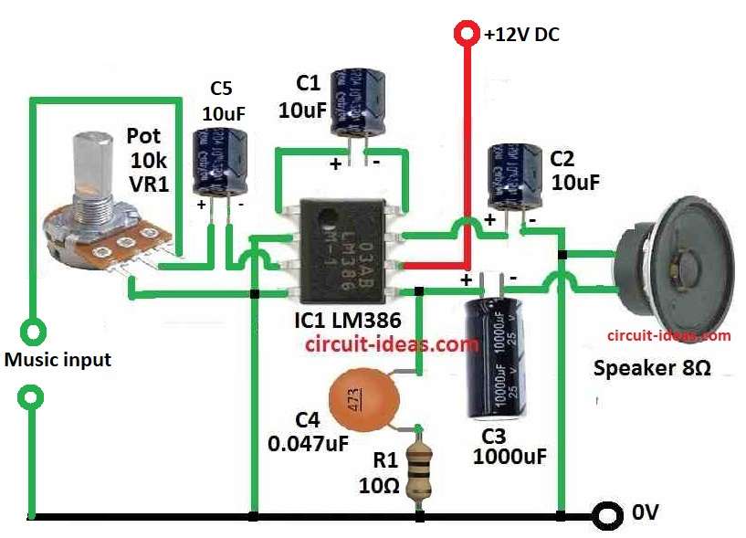
LM386 Audio Amplifier Circuit:
This circuit makes small audio signal louder so it can power a speaker, LM386 works with low voltage power between 4V to 15V, but in this project we have used 12V power supply.
To give power to the chip we have connected pin 6 (V+) to positive and pin 4 (V−) to ground.
Gain Control:
Pins 1 and 8 control the gain (loudness boost) and the circuit normally sets the gain to 20.
Also, if we put a capacitor between pin 1 and 8 we can skip the chips inside resistor and make gain go up to 200, but in this circuit we have used a 10μF capacitor for that.
Audio Input:
Audio goes into pin 2 and pin 3 and pin 2 (the inverting input) connects to ground.
Pin 3 (non-inverting input) connects to tip of 3.5mm audio jack like from phone or laptop and the sleeve outer part of the jack connects to ground.
Output Stage:
Pin 5 is output and we connect a 0.047μF capacitor to pin 5 and this capacitor blocks DC and only lets audio signal AC go to speaker and other side of this capacitor connects to positive power.
Pin 5 also connects to the speakers positive side and the speakers negative side connects to ground.
Hence, this setup lets speaker play the loud sound from the amplifier.
Bypass Capacitor:
Pin 7 is bypass pin and we have put 250μF capacitor here whichr helps remove noise from power and keeps the chip working stable.
Formulas with Calculations:
Formulas and Calculations for Simple LM386 Audio Amplifier:
1. Output Capacitor Cut-off Frequency (High-pass Filter):
We use this to find low frequency limit for audio signal going to speaker.
Formula:
fc = 1 / (2 × π × Rload × C3)
where:
- fc is cut-off frequency in Hz
- Rload is speaker resistance to 8 ohms
- C3 is output capacitor = 1000µF = 1000 × 10⁻⁶ farads
Calculation:
fc = 1 / (2 × π × 8 × 1000 × 10⁻⁶)
fc = 19.89 Hz
So the circuit blocks low frequency sounds below 19.89 Hz.
2. Zobel Network Cut-off Frequency for Stability:
Zobel network helps to keep amplifier stable and reduce noise at high frequency.
Formula:
fz = 1 / (2 × π × R1 × C4)
where:
- fz is cut-off frequency in Hz
- R1 is resistor = 10Ω
- C4 is capacitor = 0.047µF = 0.047 × 10⁻⁶ farads
Calculation:
fz = 1 / (2 × π × 10 × 0.047 × 10⁻⁶)
fz = 338600 Hz or 338.6 kHz
So the circuit filters out very high frequencies above 338.6 kHz.
How to Build:
To build a Simple LM386 Audio Amplifier Circuit follow the steps mentioned below:
LM386 Pin Connections:
- First, put LM386 chip on the PCB board and connect pin 4 to ground and connect pin 6 to +12V power supply.
Gain Control:
- Next, connect pin 1 and pin 8 using 10k resistor and to make gain of 20 put 10μF capacitor between pin 1 and 8.
- Also, if we want to change gain easily then use a potentiometer between pin 1 and 8.
Audio Input:
- Then connect pin 2 to ground and connect pin 3 to tip of 3.5mm audio jack.
- Now connect audio jack sleeve to ground.
Power Supply:
- After that pin 6 connects to positive 12V and pin 4 connects to ground.
Output Stage:
- Next, connect pin 5 to a 0.047μF ceramic capacitor, with other side of this capacitor connects to positive power.
- Also connect pin 5 to positive terminal of speaker and connect speaker negative terminal to ground.
Bypass Capacitor:
- After that connect pin 7 to a 250μF capacitor, with other side of capacitor connects to ground which helps remove noise from power.
Conclusion:
Overall, if we follow these steps then we can build a Simple LM386 Audio Amplifier Circuit that works well.
Also, we can test with different parts and change values to make sound better for our own needs.
Leave a Reply