Intercom Circuit is like smart walkie talkie for home use.
No need of button it work hands-free with electronics.
We talk in mic and it changes voice to electric signal.
Amplifier make signal strong.
One part stop our own speaker sound, so there is no echo or noise.
Same signal goes to other unit and get loud again which come from their speaker.
With this we both can hear clearly.
Knobs help control volume and reduce extra sound.
Circuit Working:
Parts List:
| Component Type | Value | Quantity |
|---|---|---|
| Resistors (All resistors are 1/4 watt unless specified) | 47k | 2 |
| 2.2k | 2 | |
| 10k | 2 | |
| 2.7k | 2 | |
| 1k | 2 | |
| 100k | 4 | |
| Potentiometer 20k | 4 | |
| Capacitors | Ceramic 100nF | 2 |
| Ceramic 10nF | 2 | |
| Ceramic 22nF | 2 | |
| Electrolytic 10μF | 6 | |
| Electrolytic 22μF | 2 | |
| Electrolytic 100μF | 4 | |
| Semiconductors | IC LM386 | 2 |
| Transistors BC547 | 2 | |
| Electret Mic | 2 | |
| 8Ω Speaker | 2 |
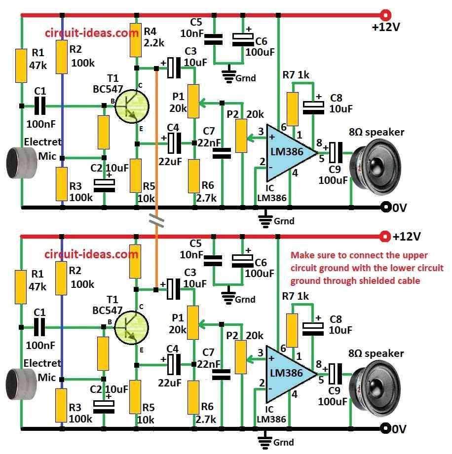
This intercom use one transistor for mic boost and LM386 IC for sound power.
Both mic and speaker are always ON so it work hands-free.
To stop feedback noise Larsen mic part flip signal 180 degree.
Signal come out from collector flipped and emitter normal.
These two signals mix with 10uF and 22uF capacitors like 2.7k resistor and 20k knob.
Mixing cancel big part of own signal so speaker stay quiet with no self-noise.
But collector of both units are connected so flipped signal goes to other unit strong and clear.
This make sound loud and clear at other speaker.
It work both ways and talk in any mic with other side hear clear sound.
User turn 20k knob to make own speaker more quiet and other sound more loud.
Second 20k knob is for volume control.
Formulas:
LM386 is IC used to make sound louder like audio amplifier.
How loud it get depends on parts resistor and capacitor between pin 1 and 8.
Formula:
Gv = 20 × Rf / Rin
- Gv is the voltage gain
- Rf is the resistor between pin 1 and 8 which controls gain
- Rin is the input resistor at pin 3
Power Gain:
Power gain is how strong sound signal becomes.
Formula:
Gp = Gv²
This show how much sound is boosted.
Knowing these formulas and how transistor boosts sound helps in making and understanding the circuit.
Final working depends on right values of resistors, capacitors and other parts.
How to Build:
To build a Intercom Circuit follow the below mentioned connections steps:
Connection of IC LM386:
- Pin 1 of LM386 connect through resistor R7
- Pin 2 connect to ground
- Pin 3 connect to P2 potentiometer
- Pin 4 connect to ground
- Pin 5 connect to speaker (8 ohm) through capacitor C9
- Other side of speaker connect to ground
- Pin 6 connect to +12V supply
- Pin 8 connect to one side of capacitor C8
Transistor T1:
- Base connect to capacitor C1
- Collector connect to +12V through resistor R4
- Emitter connect to ground through resistor R5
Mic Connection:
- One side of electret mic connect to +12V through resistor R1
- Other side connect to ground
Capacitors for Filtering:
- Capacitor C5 one side to +12V and other to ground
- Capacitor C6 one side to +12V and other to ground
Special Connections:
- Use shielded cable for orange line between upper and lower circuits
- Ground of both circuits should also connect using shielded cable
Safety Tips:
- Always check all wires and parts before switching ON
- Solder carefully and do not overheat or short
- Follow circuit diagram fully.
Conclusion:
This Intercom Circuit give hands-free talking.
One transistor boost mic sound and LM386 IC make sound strong for speaker.
The design avoid feedback noise.
This circuit is safe with low power and with clear sound.
Leave a Reply