This Echo Effect Generator Circuit tell how to make circuit for echo sound in music.
Here, transistors like BC547 create an echo effect that makes the music sound as if it is playing in a large space.
What is an Echo Effect Generator Circuit:
To make echo sound in audio we have used special electric circuit called echo effect circuit and this circuit repeat the sound after little time so it feel deep and wide.
Also, many people use this in music, audio systems and other things to make sound more nice and creative.
Circuit Working:
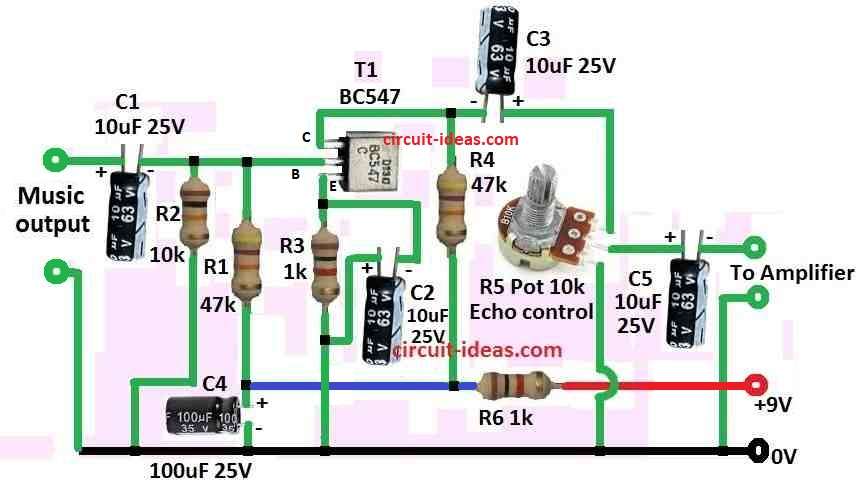
Parts List:
| Components | Values | Quantity |
|---|---|---|
| Resistors | All resistors are 1/4 W CFR | |
| 47k | 2 | |
| 1k | 2 | |
| 10k | 1 | |
| Potentiometer 10k | 1 | |
| Capacitors | Electrolytic 10µF 25V | 4 |
| Electrolytic 100µF 25V | 1 | |
| Semiconductor | Transistor BC547 | 1 |
Echo effect circuit work like this, first it make delay in sound and then mix this delay sound with real sound.
Here is the explanation of the main parts and how they work:
Delay part make small gap between real sound and repeat sound (echo) and to make delay we use capacitors, resistors or special delay parts in feedback loop.
Echo stay strong because of feedback.
Also, some delay sound go back in circuit again and make echo happen more times but slowly goes weak.
However, how many times echo happen depend on feedback level and then delay sound and real sound mix together.
Also, for this we use mixing circuit or op-amp; after a mix output gives final sound with echo.
Hence, to change echo level or strength we can use potentiometer and by change in resistance user can control how much delay sound mix with real sound.
Circuit Operation:
Echo effect happen when sound goes first to delay part and which add some time gap and then this delay sound goes to feedback loop.
Some of that delay sound goes back into circuit again hence, because of this loop echo stay and slowly get less strong.
Also, in mix step delay sound and original sound join together.
Here, potentiometer help control how much of delay and real sound mixes and after mixing output give sound with echo effect.
User can hear this echo sound by connecting output to speaker or audio system and potentiometer also help user to change echo level, more or less as they want.
Finally, this help use echo in different ways for different needs or style.
How it is Build:
To build a Echo Effect Generator Circuit follow the below steps:
- First, put BC547 transistor on breadboard or PCB.
- After that, connect base and use10μF capacitor to connect transistor base to music input.
- Also, ground base put 10Ω resistor between base and ground.
- Now add 9V power and connect 47k resistor from +9V to base.
- Use 1k resistor to limit current from 9V and after 1k resistor use 100μF capacitor to filter.
- Collector connection from 1k resistor and add 47k resistor and then connect to collector of transistor.
- Add potentiometer and put 10k potentiometer between collector and ground.
- Then the output wire connects to center pin of potentiometer.
- Now adjust echo and use 10μF capacitor from center pin of potentiometer to ground.
- Lastly, power the circuit and give 9V power to whole circuit.
Testing:
- Turn on and check if circuit work and change potentiometer to adjust echo sound.
- We can connect center pin output to external speaker amplifier and turn potentiometer left or right until echo sound is good.
Important:
- Check all wires and connections and ensure capacitor side positive and negative sides are correct and fix if something is not working.
Conclusion:
Overall, this Echo Effect Generator Circuit make delay sound from audio input.
Also, feedback loop keeps echo going and potentiometer help control how much echo mixes in sound.
Hence, after finish we can use this in music system for cool echo effect!

Leave a Reply