• Skip to primary navigation
  • Skip to main content
  • Skip to primary sidebar

Circuit Ideas for You

Get free circuit ideas online.

  • Home
  • Privacy Policy
  • About
Home » Transistors Based Megaphone Circuit

Transistors Based Megaphone Circuit

Last updated on 18 June 2026 by Admin-Lavi Leave a Comment

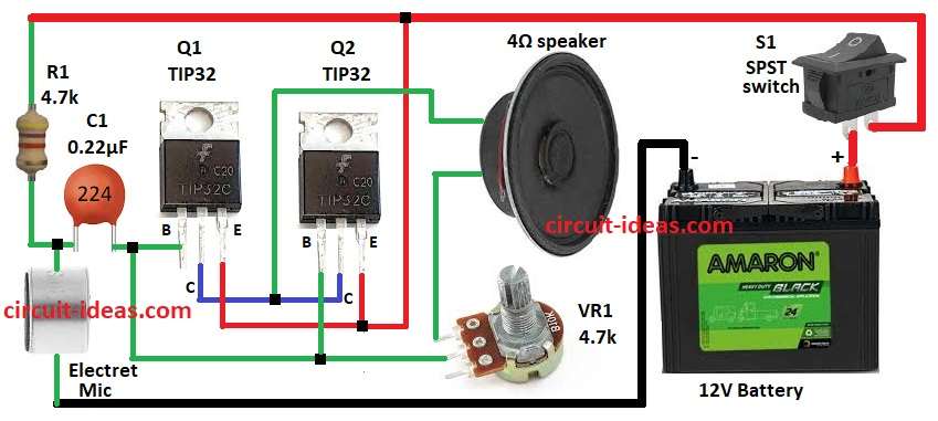
To begin with, this Transistors Based Megaphone Circuit uses transistor like amplifier, as it take weak sound from MIC and makes loud sound in speaker.

People also use it in public talks, sports events and rallies wherever they need a loud voice; the circuit additionally uses two TIP32 transistors in a push-pull configuration to boost the sound.

Also the circuit work with 12V battery or 12V DC power.

Circuit Working:

Transistors Based Megaphone Circuit Diagram

Parts List:

ComponentsValuesQuantity
Resistors4.7k 1/4 watt1
Potentiometer 4.7k1
CapacitorCeramic 0.22µF1
SemiconductorsTransistors TIP322
Electret Microphone1
SPST Switch1
Speaker1
Battery1

Electret mic is very important in this circuit as it change sound wave to small electric signal.

Here, Q1 TIP32 work like preamp and make mic signal stronger and then signal goes to Q2 TIP32 power amp and make sound more strong for speaker.

Then 4Ω speaker change signal back to loud sound and then VR1 control volume and user adjust the loudness.

Furthermore, C1 block DC and pass mic frequency to transistor base, R1 give bias to mic circuit and then finally, S1 is power switch for whole circuit.

Circuit uses 12V battery and is easy to carry and use.

Formulas with Calculations:

Below are the formulas with calculations for Simple Transistors Based Megaphone Circuit:

Voltage gain:

Av = β × (RL / RE)

where,

  • β for TIP32 is 25 to100
  • RL is for 4Ω speaker
  • RE is for emitter resistor.

Power output:

P = V² / R

V = 10V and R = 4Ω

P = 100 / 4 = 25W.

Current from battery:

I = P / V

P = 25W and V = 12V

I = 25 / 12 = 2.08A.

How to Build:

To build a Transistors Based Megaphone Circuit follow below steps for connection:

  • First, gather parts from circuit diagram.
  • Next, connect MIC to Q1 base through C1 and other MIC pin to GND.
  • Then connect R1 between C1, MIC and positive supply.
  • Now connect Q1 collector to Q2 collector., connect Q1 emitter to Q2 emitter and positive supply and then Q1 & Q2 base go to middle pin of VR1.
  • After that, VR1 second pin goes to 4Ω speaker and other speaker pin goes to collectors of Q1 & Q2.
  • Finally, S1 switch goes between positive supply and 12V battery and battery negative go to GND.

Conclusion:

Overall, this Transistors Based Megaphone Circuit is easy and small megaphone for announcements, also transistor TIP32 push-pull give clear sound.

Moreover, it work on 12V battery portable and VR1 adjust volume and is simple to use.

Filed Under: Amplifier Circuits, Audio Circuits, DIY Projects, Transistor Circuits

About Admin-Lavi

Lavi is a B.Tech electronics engineer with a passion for designing new electronic circuits. Do you have questions regarding the circuit diagrams presented on this blog? Feel free to comment and solve your queries with quick replies

Previous Post: « Adjustable Thermostat Circuit using IC LM56
Next Post: Different Types of LEDs: A Comprehensive Guide »

Reader Interactions

Leave a Reply Cancel reply

Your email address will not be published. Required fields are marked *

Primary Sidebar


Categories

  • 555 Timer Projects (123)
  • Alarm Circuits (75)
  • Amplifier Circuits (92)
  • Arduino Projects (103)
  • Audio Circuits (189)
  • Automation Circuits (113)
  • Automobile Circuits (38)
  • Battery Charger Circuits (86)
  • DIY Projects (368)
  • Free Energy (12)
  • Heater and Temperature Controllers (32)
  • High Voltage (23)
  • Hobby Circuits (198)
  • Indicator Circuits (62)
  • Inverter Circuits (18)
  • IoT projects (10)
  • LDR Circuits (45)
  • LED and Lamps (196)
  • Meters and Testers (43)
  • Mini Projects (299)
  • Motor Controllers (25)
  • Oscillator Circuits (63)
  • Power Supply Circuits (228)
  • Radio Frequency (7)
  • Remote Control Circuits (11)
  • Renewable energy (13)
  • Security and Protection (108)
  • Sensors and Detectors (224)
  • Solar Circuits (31)
  • Timer Circuits (62)
  • Transistor Circuits (176)
  • Transmitter Circuit (19)
  • Tutorials (29)
  • Voltage Regulator (38)
  • Water Level Controller (10)

Recent Posts

  • Low Current Controlled Battery Charger Circuit using LM723 IC
  • 741 Op-Amp Treble Booster Circuit
  • Simple Diode and Transistor Based Audio Limiter Circuit
  • Simple 500mW Speaker Driver Circuit
  • Easy DIY LM386 Audio Amplifier Circuit

Recent Comments

  1. Tony Gallegos on NTC Thermistor Based Temperature to Voltage Converter Circuit
  2. colin on Simple Single Transistor Audio Amplifier Circuit
  3. How to Make a Bird Chirping Noise Easily on Chirping Bird Sound Generator Circuit
  4. Transistor Based Medium Impedance Preamplifier Circuit - Circuit Ideas for You on Low Impedance Input Transistor Preamplifier Circuit
  5. Admin-Lavi on Alternate Red Green LED Flasher Circuit

Copyright © 2026 | New Circuit Ideas