This easy LED circuit with Joule Thief can make light from a weak 1.5V battery, also it works with white, blue and UV LEDs.
Further, we only need a low power battery like 1.2V, even better the LED still glows even if the battery is very low like 0.4V.
So now we can use old batteries which people throw away.
However, making the circuit can be dangerous, therefore, do it only with help of an experienced person or expert.
What is a Joule Thief Circuit:
Joule Thief circuit is small voltage booster and it can take weak battery and make power strong again.
Also, the idea is simple which uses few parts to make low battery and to give more power, even if the battery is almost dead, it still can run small things with this circuit.
Circuit Diagram:
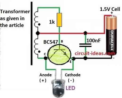
Parts List:
| Components | Values | Quantity |
|---|---|---|
| Resistor | 1/4 W CFR 1k | 1 |
| Capacitor | Ceramic 100nF | 1 |
| Semiconductors | Transistor BC547 | 1 |
| Battery 1.5V AAA Cell | 1 | |
| LED 5mm 20mA | 1 | |
| Transformer As explained in article | 1 |
Formulas and Calculations:
Coil Turns (N): N = 2 × 50 turns
Make two coil winding each 50 turn.
Coil Wire Thickness (d):
Wire size: 0.05 mm to 0.2 mm
Use thin copper wire like hair.
Ferrite Core Area (A):
A = 7 mm² Middle part of coil is 7 mm².
Work Frequency (f):
f = around 50 kHz Circuit works at high speed like 50,000 times in 1 second.
Construction of ferrite core:
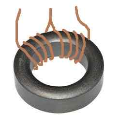
Coil Winding:
- First, take ferrite core ring (donut shape) like shown above.
- Next, take thin copper wire and wind 2 wires together 50 turns each, total 2 × 50 turns.
- Then, wind both wires at same time for better working, wire size can be 0.05 mm to 0.2 mm.
Core Assembly:
- After winding coil use super glue to stick both ferrite cores together, be sure it is strong and not loose.
Circuit Connection:
- Now, connect this coil to the Joule Thief circuit.
- Joule Thief is self-oscillating inverter which it works by turning ON and OFF fast.
Frequency Adjust:
- Try to adjust circuit near 50 kHz (50,000 times per second), it is not necessary, but this frequency gives the best result.
Capacitor (Optional):
- If capacitor is not needed then we can add if want.
- To find capacitor value use this formula: C = 1 / (2πfZ) where, f is the frequency and Z is the circuit impedance
Enclosure Making:
- Take old broken torch like flashlight.
- Remove small bulb and 2 AA batteries.
- Put Joule Thief circuit where second battery was before.
Power Source:
- Use only 1 battery of 1.5V or 1.2V max.
- LED can start glow from 0.4V power which is very low
Voltage Idea:
Working Frequency:
- Joule Thief work around 50 kHz speed, but this is not must, the circuit still works without exact frequency.
Capacitor (Optional):
- We can put capacitor but if not needed, circuit still works good without it.
Safety Tips:
- First, check all wire connection two times before turning ON and use good soldering with no loose parts.
- Use parts with correct voltage and current numbers for ratings.
- Also, follow safety to be sure circuit works safe and strong.
- Now with this we can use old 1.5V battery to light LED again!
Conclusion:
This Light Up LED with Weak 1.5V Battery using Joule Thief Circuit is smart way to use weak batteries, even people think batteries are dead, but it can still glow LED!
Steps and parts in this post help to make it easy.
Leave a Reply