In this Stun Gun, Taser Gun Circuit, people use Tasers (or stuns) to deliver a powerful shock that stops an assailant.
Here, the shock is to scare and hurt but not to kill.
Bad person may not be in position to control his body for few seconds after shock and at that time we can run away.
Also, if you shock them for more than 1 second, they might fall down and not move for some minutes, but our main goal is not to hurt them badly, but just to escape.
WARNING: If used in the wrong way, a stun gun can be dangerous and it is not a toy, so it is better to avoid fights if possible.
What is a Stun Gun, Taser Gun Circuit:
Stun gun or Taser gun is electric device which makes person weak for short time by giving electric shock.
Stun gun and Taser are little different but both use high voltage and low current shock and this shock confuse the muscles and nerves and person feel trouble to move for short time.
The working principle of stun gun circuit:
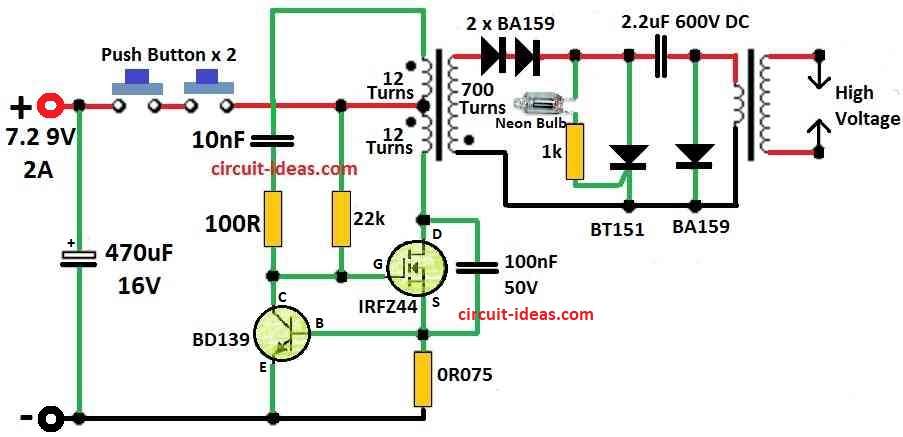
Parts List:
| Components | Values | Quantity |
|---|---|---|
| Resistors ( All resistors are 1/4 W MFR) | ||
| 100Ω | 1 | |
| 22k | 1 | |
| 1k | 1 | |
| 0.75Ω | 1 | |
| Capacitors | ||
| Electrolytic 470uF 16V | 1 | |
| PPC 10nF 50V | ||
| PPC 100nF 50V | 1 | |
| PPC 2.2μF 600V | 1 | |
| Semiconductors | ||
| Diode BA159 | 1 | |
| SCR BT151 | 1 | |
| Transistor BD139 | 1 | |
| MOSFET IRFZ44 | 1 | |
| Neon Bulb | 1 | |
| Push Button | 2 |
Here, the stun gun work like voltage changer.
Firstly, battery voltage goes high like few hundred volts to few thousand volts using high frequency transformer and this high voltage charge a capacitor.
After capacitor is full it gives power to second transformer and then voltage goes more high like 10 to 50 thousand volts.
Secondly, numbers on stun gun like 100,000V or 200,000V is not real, because if 200,000V was true then spark would go more than 2 meters.
Company just write big number to look strong and normal people do not know about this.
Stun gun pulse happen 5 to 40 times in one second.
Formula:
A circuit can make voltage go higher by using this formula:
Vout = (2Vin + 1.414) × S
where:
- Vout represents output voltage and Vin represents input voltage.
- 2Vin means input voltage goes double.
- 1.414 is maybe square root of 2 which come from circuit design.
- S is scaling number and we can change it to make more or less voltage.
Different type of stun guns:
There are 3 main types:
- Thyristor (SCR)
- Spark gap
- Multiplier
Cheap stun guns use spark gap and they do not work good and are not reliable.
But in these, a spark gap replaces the thyristor and a transistor converter increases the battery voltage.
To make spark gap work voltage must go minimum 1,000 volts (1kV).
Sometimes first transformers second part has extra multiplier to help.
When capacitor charge high enough it makes spark gap work and send power to pulse transformer capacitor this works similar like Tesla coil.
Also, if we use a thyristor SCR instead of a spark gap, the stun gun works better and costs less.
Here, the capacitor voltage is around 250 to 500V and we can start the SCR using a diac, neon lamp or resistor divider.
Multiplier stun guns uses one transformer that gives big voltage and then diode and capacitor cascade make it more high which gives DC voltage (not pulses).
The sound of spark come from multiplier capacitors.
But if capacitors touch skin directly they give continuous shock but not pulses and this make stun gun less strong.
So, it better not to touch attackers body but just put electrodes near the body and not on it.
My Stun Gun:
I choose thyristor SCR type, in market many stun guns use bipolar transistor push-pull converters but they have only 20% efficiency.
So, I have made my own voltage converter with MOSFET which gives around 75% efficiency.
Working frequency is between 80 to 120 kHz.
Circuit uses 4 neon glow lamps in series to start thyristor and these lamps make about 95V each total around 380V.
Thyristor is second switch, whose pulse rate is around 30 to 50 times per second (Hz).
We make the inverter transformer on a ferrite EE core with a 20 to 25 mm² middle column and a 0.5 mm air gap in the center column.
Primary wire is 2 wires x 12 turns and secondary coil has 700 turns with 0.1 mm wire, because voltage is high coil secondary should be in many small layers.
If not wire enamel can break and it is very important to keep secondary polarity correct.
Making high voltage pulse transformer several kV is not easy.
The circuit uses this high-voltage transformer for a xenon strobe light and provides two transformers, with their primaries connected in parallel and their secondaries in series.
My stun gun has two types of electrodes:
First, test electrodes they are close together and when there is no load small spark goes out and it control max voltage and also warn attacker.
And the second is main electrodes they face forward and these are farther apart than test ones and they send electricity into attacker body.
Power comes from six 1.5V batteries or six to seven 1.2V NiCd or NiMH batteries.
Better way is to use two Li-ion or Li-pol cells in series (2 x 3.6–3.7V).
Stun gun uses high current to about 1.5A so normal 9V battery will not work.
Important Note:
This guide is only to show how stun gun works which is not for real use, so not use on people or animals whose do not harm you.
Output voltage is very dangerous and it can cause serious injury or even death.
Even after we remove battery the capacitor still have charge.
Remember, children must not use or keep this device and if we test stun gun we should do it at our own risk.
Also, the maker of this page is not responsible for any injury as all things in this article are for ones own learning only and own risk.
Safety Measures:
To work with stun gun circuits we must know about high voltage safety as small mistake can make big danger.
Only experienced people who know the risks and have right tools should build this kind of device.
Good stun gun designs have safety parts like:
- Switch to turn OFF fully
- Resistors to stop too much current
- Insulation to stop shock
These things help avoid accidents and injuries.
Conclusion:
To conclude, if someone play with Stun Gun Taser Gun Circuit like making or changing just know it can make them fall in big legal trouble.
So always be very careful with safety first and do not break the law and better to learn and not to create any problem.
Leave a Reply