Capacitive Discharge Ignition (CDI) Circuit is like small engine lighter, which keeps power like balloon and then release fast boom!
It creates a strong spark that burns the fuel and many bikes, cutters and older cars use this type of circuit.
Circuit Working:
Parts List:
| Components | Values | Quantity |
|---|---|---|
| Resistors | 100Ω 1W | 1 |
| 56Ω 1W | 1 | |
| Capacitors | PPC 105 400W | 1 |
| Semiconductors | SCR BT151 | 1 |
| Diodes 1N4007 | 3 | |
| Ignition coil | 1 | |
| High tension wire to spark plug | 1 |
To begin with, this post show an easy way to make CDI (Capacitive Discharge Ignition) system using normal ignition coil and SCR circuit.
Also, ignition system is important but make spark to burn fuel and start engine.
Moreover, older cars used breakers for this job, but most modern cars now use a better system called CDI.
How CDI Work:
CDI take two power signals:
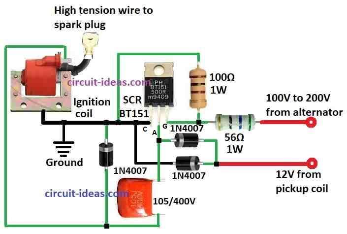
- One big voltage with 100 to 200V AC which come from alternator
- One small voltage with 10 to 12V AC which come from pickup coil
The large voltage changes to DC first and then charges the capacitor.
Then, a small voltage pulse reaches the SCR, causing it to turn on and send power from the capacitor to the ignition coil.
Ignition coil boosts the voltage to a very high level and next, sends it to the spark plug.
Finally, the spark plug creates a spark, which starts the engine.
Why CDI Good:
The alternator alone does not provide enough power, so the CDI stores energy and releases it quickly to create a strong spark.
The ignition coil works like a transformer and increases the voltage; as a result, the CDI helps the engine start more easily and run more efficiently.
Formulas:
To make a high voltage spark a CDI circuit stores power in a capacitor and then quickly sends it through the ignition coil.
Basic formulas to understand:
1. Charging the Capacitor:
Voltage across capacitor over time:
Vc(t) = Vs * (1 – exp(-t / (R * C)))
- Vs is the power supply voltage
- R is the resistance
- C is the capacitance
- exp is the exponential a math function
2. Energy Stored in Capacitor:
E = 0.5 * C * V²
- E is the energy
- C is the capacitance
- V is the voltage
3. Voltage in an Inductor (like ignition coil):
Vl = L * (di/dt)
- Vl is the voltage across inductor
- L is the inductance
- di/dt is how fast current is changing
Note:
Finally, if we understand these formulas we can design our own CDI circuit and we can change the values of components like resistors, capacitors and coils based on what we need our circuit to do.
How to Build:
To build a Capacitive Discharge Ignition CDI Circuit follow the below mentioned steps:
- First, connect SCR cathode to ground.
- Next, put one 1N4007 diode between ground and capacitor 105 400V.
- Join two 1N4007 diodes in line series from ground to SCR anode.
- Now put 100 ohm resistor between SCR gate and ground.
- Then connect one side of 56 ohm resistor to SCR gate and other side to high voltage AC from alternator.
- Also, connect one side of capacitor 105 400V to SCR anode and other side to primary wire of ignition coil.
Conclusion:
To conclude, Capacitive Discharge Ignition (CDI) Circuit is smart circuit to make strong spark to start a engine.
Furthermore, it gives more hot spark, better work and easy start than old system; but it is little hard and can damage easily, so it is better for bike and small engine only.
Leave a Reply