Do need very perfect and steady beat for song? then this Simple Pierce Oscillator Circuit is like music tool that gives same note every time but very correct.
Also, it uses special crystal like tuning fork to make very stable signal with right frequency and that is why many electronics use it like clocks because it keep rhythm same always.
Circuit Working:
Parts List:
| Components | Values | Quantity |
|---|---|---|
| Resistor | 120k 1/4 watt | 1 |
| Capacitors | Ceramic 0.001µF | 1 |
| Semiconductors | FET BS170 | 1 |
| Quartz Crystal | 1 | |
| ON/OFF Switch | 1 | |
| RF Choke 2.5mH | 1 |
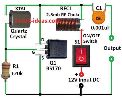
Nice thing about Pierce oscillator is it works good, without need to adjust or fine tune and in above circuit diagram the circuit uses simple transistor BS170 and few more parts.
Here, the Crystal XTAL is like heart of circuit which controls the exact frequency.
Choke RFC1 does not changes the frequency but it stops bad RF signals from going to power so circuit can run smooth.
When we turn ON the switch S1 the circuit starts working by itself and makes steady signal from crystal.
Capacitor C1 connect output to other device and it also stop too much current from going out and keep oscillation safe.
Furthermore, circuit uses a very low current with only about 2.3 mA from 12V power.
Note: The Pierce oscillator uses the crystal’s primary frequency, forcing the circuit to ignore harmonics and operate solely at the main frequency.
Also, crystal must be strong and active to make circuit work well.
Formulas:
In Pierce oscillator crystal decide the main frequency.
How to Know Frequency:
Crystal part control how fast circuit oscillate.
Use this formula to find frequency:
f = 1 / (2 × π × √(L × C))
where:
- L is like RF choke is inductance part.
- C is like capacitor C1 which works with crystal and affect total load capacitance.
Note:
If we follow these rules and understand basic math then we can build our own transistor crystal oscillator for any frequency we need.
Hence, we can change part values and design based on our needs and how good we want it to work.
How to Build:
To build a Simple Pierce Oscillator Circuit follow the below mentioned steps for assembling:
Check Parts:
- Check capacitor C1 and C2 are right for our crystal frequency and look at crystal and transistor datasheets and check they give helpful details.
Be Safe:
- Soldering is hot and can burn then be careful and if anyone is beginner try building on breadboard first, before doing solder.
Start Easy:
- Begin with simple circuit and easy to find parts and then try small first and then go to big or complex circuits.
Note:
Pierce oscillator look simple but always be safe with electronics, if anyone is not sure about something ask someone who knows it more like hobbyist or expert.
Conclusion:
Overall, Simple Pierce Oscillator Circuit is easy and good way to make stable signal at fixed frequency, as it uses few parts and crystal make it very steady.
Also, many electronic devices use it because of its simple design and low power consumption.
Leave a Reply