A triangle wave is one that rises, falls, rises again, and so on.
It is a unique type of wave composed of harmonics, which are smaller waves.
The triangular shape is formed by stacking these smaller waves, which are similar to building bricks.
The harmonics of a triangle wave weaken far more quickly than those of a square wave, which have very strong harmonics.
This indicates that compared to a square wave, it is smoother and has less sharp corners.
In many applications, such as signal processing, waveform production, and testing apparatus, a triangle wave generator is a necessary circuit.
In this article, the LM358 op-amp and its required parts, including resistors and capacitors, are designed to create a triangle wave generator.
The DC supply range for the circuit is 5V to 9V.
Circuit Working:

Parts list:
| Component Type | Value | Quantity | Wattage |
|---|---|---|---|
| Resistor | 1k | 3 | 1/4 watt |
| Resistor | 10k | 1 | 1/4 watt |
| Resistor | 100k | 1 | 1/4 watt |
| Capacitor (Electrolytic) | 10µF 25V | 1 | – |
| Capacitor (Ceramic) | 0.1µF | 1 | – |
| Semiconductor | IC LM358 | 1 | – |
| DC Power Supply | 5V to 9V | 1 | – |
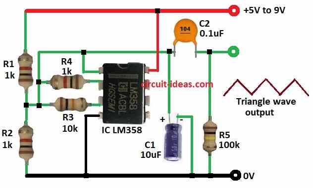
The main component in this circuit is an operational amplifier configured as an integrator combined with a Schmitt trigger.
The op-amp from the IC LM358, along with resistors R1, R2, and R3, forms the Schmitt trigger.
This setup generates a stable square wave output by changing the output state when the input voltage crosses certain threshold levels.
The positive feedback through resistor R3 adds hysteresis, ensuring the op-amp switches cleanly between high and low states, producing the square wave.
Additionally, the op-amp acts as an integrator using resistor R4 1k and capacitor C1 10µF connected to the inverting input.
This integrator takes the square wave output from the Schmitt trigger at pin 1, and converts it into a triangular waveform by integrating the input signal.
As a result, the output voltage ramps up and down continuously, creating the triangular wave.
Formulas:
The following relevant formulas are based on how the LM358 op-amp-powered triangle wave generating circuit operates:
Schmitt Trigger Formulas
- Threshold Voltages (Vth+ and Vth-):
Positive Threshold Voltage: Vth+=Vref+(R2 / R1+R2) x Vcc)
Negative Threshold Voltage: Vth−=Vref−(R2 / R1+R2) x Vcc)
where,
2. Hysteresis (ΔV): ΔV = Vth+ − Vth−
3. Integrator Formulas:
Frequency (f): f =1 / T = 1 / 2RC
where,
- R = R4 resistor in the integrator
- C= C1 (capacitor in the integrator)
4. Period (T): T = 2RC
5. Slope of Triangular Wave: Slope = Vmax−Vmin / T/2
where,
- Vmax and Vmin are the peak and trough voltages of the triangular waveform.
Output Voltage for Integrator
6. Output Voltage (Vout): Vout(t) = ∫ Vin(t)dt
This illustrates how the voltage continuously ramps up and down to create the triangle waveform.
Based on the LM358 op-amp design, these formulas allow you to examine and forecast the behavior of the triangle wave generating circuit.
How to Build:
To build a Simple Triangle Wave Generator Circuit using IC LM358 follow the below mentioned steps for connections:
- Assemble all the components mentioned in the above circuit diagram.
- Connect pin 1 of IC LM358 to triangle wave output through capacitor C2.
- Connect pin 2 to pin 1 of IC LM358 through resistor R4.
- Connect pin 3 to pin 1 of IC LM358 through resistor R3.
- Connect pin 4 of IC LM358 to GND.
- Connect pin 8 of IC LM358 to positive supply.
- Connect resistor R1 and R2 from positive supply to GND, connect pin 3 of IC LM358 between resistor R1 and R2.
- Connect capacitor C1 between pin 1 of IC LM358 and GND.
- Connect resistor R5 to the output terminal of C2 and GND.
Conclusion:
The LM358 op-amp based triangle wave generator is a simple, effective circuit that may be built with easily accessible parts.
The frequency and amplitude of the output waveform may be readily changed to fit particular applications by adjusting the values of the resistor and capacitor.
It is an invaluable tool for electronics design and experimentation because of its adaptability.
References:
Building a triangle wave generator using two LM358 with single supply operation
Leave a Reply