Making nice looking projects help learning and fun in electronics.
Simple Arduino-Powered Running LED Circle Circuit is one easy project which uses Arduino to control LEDs in a circle.
Also, this project is simple and it teaches coding, circuit making and LED control, here, a 10k pot changes LED speed and makes it fun to use.
Arduino Code:
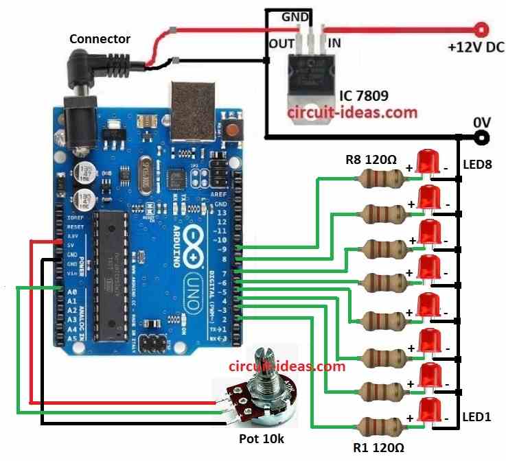
Arduino Pin 2  ----|120Ω|----|>| LED1
Arduino Pin 3  ----|120Ω|----|>| LED2
...
Arduino Pin 9  ----|120Ω|----|>| LED8

A0 ------|------- Potentiometer -------|--- 5V
                 |--- GND (other pin)

                 |---- 7809 ---- Power rail for LEDs
const int ledPins[] = {2, 3, 4, 5, 6, 7, 8, 9}; // Define LED pins
const int potPin = A0; // Define potentiometer pin
int potValue; // Variable to store potentiometer value
int delayTime; // Variable to control delay based on pot value

void setup() {
  // Initialize LED pins as outputs
  for (int i = 0; i < 8; i++) {
    pinMode(ledPins[i], OUTPUT);
  }
}

void loop() {
  potValue = analogRead(potPin); // Read the potentiometer value (0-1023)
  delayTime = map(potValue, 0, 1023, 50, 500); // Map it to a delay range (50ms to 500ms)

  for (int i = 0; i < 8; i++) {
    digitalWrite(ledPins[i], HIGH); // Turn on the current LED
    delay(delayTime); // Wait for a duration based on potentiometer
    digitalWrite(ledPins[i], LOW); // Turn off the current LED
  }
}
Code Explanation:
- The LED pin numbers are stored in the
ledPinsarray. - In setup() each LED pin set as output.
- In loop() it reads potentiometer, changes delay time and turns on LEDs one by one with that delay.
Circuit Working:
We can arrange the above LEDs in circle as shown below:

Parts List:
| Components | Quantity |
|---|---|
| Resistors | |
| 1/4 watt 120Ω | 8 |
| 10k Potentiometer | 1 |
| Semiconductors | |
| Arduino UNO Board | 1 |
| IC 7809 Voltage Regulator | 1 |
| LEDs Red any color | 8 |
This project connects IC 7809 input to Arduino 5V and output to breadboard rail for LEDs.
Verify that the ground pins are connected correctly and also, this circuit is easy to build with only a few components.
Furthermore, a 10k potentiometer controls LED speed, its middle pin goes to Arduino A0.
Then Arduino reads pot value when power is ON and it changes delay between LED lights; after that turning pot can change LED speed and through this LEDs light in circle and looks nice.
Therefore, this simple project teaches basic code, electronics and circuit making.
How to Build:
To build a Simple Arduino-Powered Running LED Circle Circuit follow the below mentioned connections steps:
- First, gather all parts shown in circuit diagram.
- After that, use IC 7809 to give 9V DC to Arduino which is as in circuit diagram above.
- The place 8 LEDs from LED1 to LED8 in circle on breadboard.
- Now connect 120Ω resistor to anode of each LED and then connect cathode of each resistor to ground.
- Also other side of each resistor goes to Arduino pins from 2 to 9.
- Next, middle pin of potentiometer goes to analog pin A0, one side of pot goes to 5V and other side go to GND.
Conclusion:
Overall, Simple Arduino-Powered Running LED Circle Circuit is great to start learning Arduino and electronics; also it shows how to use simple parts like pot, LEDs and regulator to make fun and changeable display.
Hence, this project is good for beginners or anyone who wants to refresh skills.
Leave a Reply